Magnetic core and applicable magnetic element of magnetic core

A technology of magnetic components and magnetic cores, applied in the direction of inductors with magnetic cores, transformer/inductor cores, etc., can solve the problem of high difficulty in heat dissipation, insufficient distance between winding wire package and winding frame, and wire diameter of winding coils minor issues

Inactive Publication Date: 2014-12-31
DELTA ELECTRONICS INC
View PDF5 Cites 2 Cited by
  • Summary
  • Abstract
  • Description
  • Claims
  • Application Information

AI Technical Summary

Problems solved by technology

[0005] The main purpose of the present invention is to provide a magnetic core and its applicable magnetic components, so as to solve the problem that the existing magnetic core adopts a circular central column structure, which causes the winding space to be small, the wire diameter of the windin...

Method used


Image

  • Magnetic core and applicable magnetic element of magnetic core
  • Magnetic core and applicable magnetic element of magnetic core
  • Magnetic core and applicable magnetic element of magnetic core

Examples


Embodiment Construction

[0036] Some typical embodiments embodying the features and advantages of the present invention will be described in detail in the description in the following paragraphs. It should be understood that the present invention can have various changes in different aspects without departing from the scope of the present invention, and the descriptions and illustrations therein are used as illustrations in nature rather than limiting the present invention .

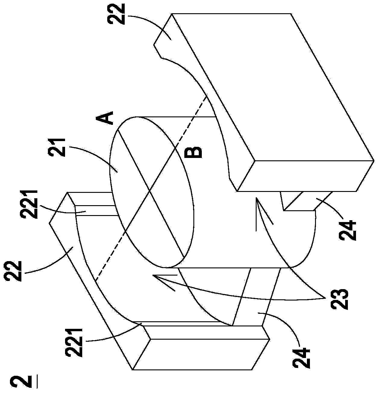
[0037] see Figure 2A and Figure 2B ,in Figure 2A It is a structural schematic diagram of a magnetic core in a preferred embodiment of the present invention, Figure 2B for Figure 2A A top view of the magnetic core shown. Such as Figure 2A and Figure 2B As shown, the magnetic core 2 of the present invention at least includes an elliptical central column 21 and two side columns 22 . The elliptical central column 21 has a major axis A and a minor axis B, and the length of the major axis A is greater than the length of...


PUM


Abstract

The invention discloses a magnetic core and an applicable magnetic element of the magnetic core. The magnetic core at least comprises an oval center post and two side posts, wherein the oval center post is provided with a long shaft and a short shaft; the length of the long shaft is greater than that of the short shaft; the two side posts are oppositely arranged at two sides of the oval center post, are connected with the oval center post, and define at least one winding space together with the oval center post. Through the arrangement of the oval center post, the magnetic core has the advantages that the winding space is enlarged, the diameter of a wining coil is increased, the temperature of a winding solenoid is lowered, the winding solenoid is prevented from being oversize, and the safety distance between the winding solenoid and a reel is increased to accord with the safety specification.

Description

technical field [0001] The invention relates to a magnetic core, in particular to a magnetic core with an elliptical central column structure and an applicable magnetic element. Background technique [0002] Magnetic components are indispensable basic components for the operation of electronic devices, and can be widely used in various electronic devices. With the development trend of miniaturization, high power, multi-function and popularization of electronic devices, magnetic components must also be designed in a flat design, improve overall performance, increase structural diversity and reduce costs to meet the needs of electronic devices. [0003] see Figure 1A , which is a schematic diagram of a magnetic core structure applied to an existing magnetic element. Generally speaking, the magnetic core 1 has a central column 11 and two side columns 12 , and the central column 11 and the two side columns 12 define a winding space 13 for coil winding. Please also see Figur...

Claims


Application Information

Patent Timeline
IPC IPC(8): H01F27/24H01F17/04
Inventor 林汉星赖育骏陈义霖刘家铭陈志明刘建宏
Owner DELTA ELECTRONICS INC
Why Eureka
Try Eureka