Stent delivery system

a technology of stent and stent body, which is applied in the field of stent delivery system, can solve the problems of the minimum constrained diameter of the stent, the use of the helically joined stent, etc., and achieve the effects of improving the push (or pull) strength of the catheter, effective delivery, and maintaining flexibility and pushability

Inactive Publication Date: 2007-02-06
BOSTON SCI SCIMED INC
View PDF65 Cites 199 Cited by
  • Summary
  • Abstract
  • Description
  • Claims
  • Application Information

AI Technical Summary

Benefits of technology

[0014]In a preferred embodiment, the inner shaft is formed of steel braided tube encased in a polyimide. For low profile stent delivery systems, where the smaller diameter of the body lumen or the smaller diameter of the endoscope delivery channel necessitate improvements in the Push (or pull) strength of the catheter, the use of a braided tube to maintain flexibility and pushability without kinking provides effective delivery of low profile stents.
[0015]In the embodiments described above

Problems solved by technology

A limitation on the use of the helically joined stent involved

Method used


Image

  • Stent delivery system
  • Stent delivery system
  • Stent delivery system

Examples


Embodiment Construction

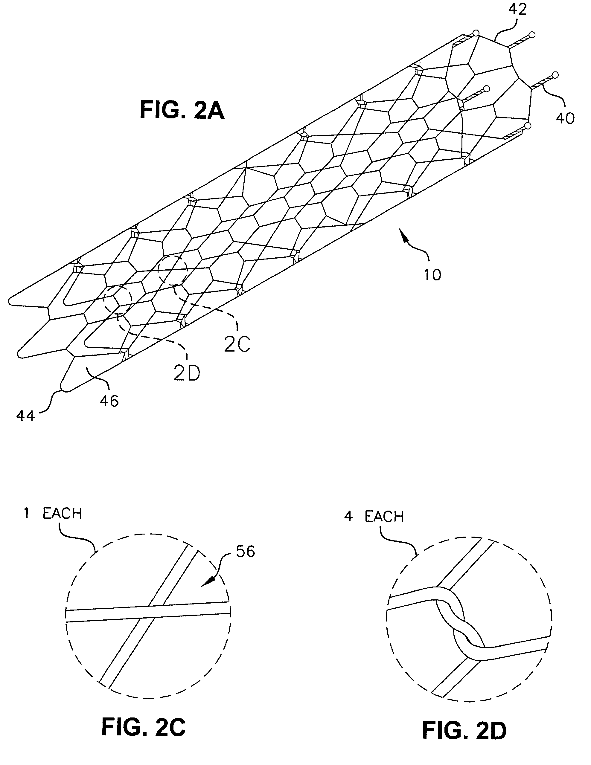
[0067]Referring to the drawings in detail, where like numerals indicate like elements there is illustrated an implantable prosthesis in accordance with the present invention designated generally as 10.

[0068]Medical prostheses, such as a stent 10 according to the invention, are placed within the body to treat a body lumen that has been impaired or occluded. Stents according to the invention are formed of wire configured into a tube and are usually delivered into the body lumen using a catheter The catheter carries the stent in a reduced-size form to the desired site. When the desired location is reached, the stent is released from the catheter and expanded so that it engages the lumen wall as explained below.

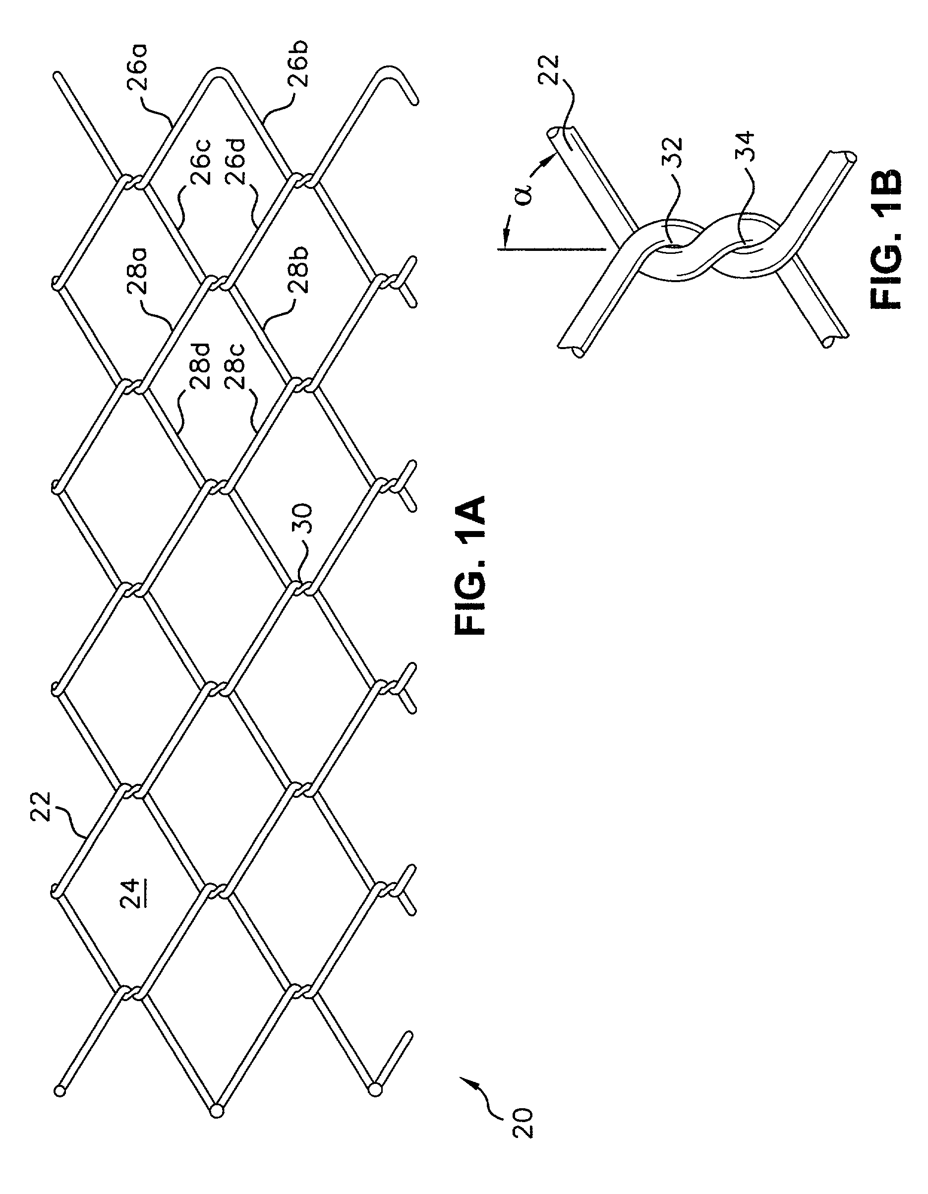
[0069]A stent 20 is shown in a flat layout view in FIG. 1A. The stent 20 is formed of elongated strands 22 such as elastic metal wires. The wires 22 are woven to form a pattern of geometric cells 24. The sides 26a, 26b, 26c, and 26d of each of the cells 24 are defined by a series...


PUM


Abstract

The present invention relates to a system for delivering a medical prosthesis into a body lumen. A preferred embodiment of the invention utilizes a catheter having a stent mounted at the distal end that is released into the body lumen by movement of an outer sheath covering the stent in the proximal direction. The stent expands to conform to the inner wall of the lumen and the catheter is withdrawn.

Description

RELATED APPLICATION[0001]This application is a division of U.S. patent application Ser. No. 09 / 270,949 filed on Mar. 17, 1999, now U.S. Pat. No. 6,520,983 and which is a continuation-in-part of U.S. patent application Ser. No. 09 / 052,214, filed on Mar. 31, 1998 now U.S. Pat. No. 6,264,689, the entire teachings of which are incorporated herein by reference.BACKGROUND OF THE INVENTION[0002]Implantable medical prostheses, such as stents, are placed within the body to maintain and / or treat a body lumen that has been impaired or occluded, for example, by a tumor The stent can be formed of strands of material formed into a tube and are usually delivered into the body lumen using a catheter. The catheter carries the stent to the desired site and the stent is released from the catheter and expands to engage the inner surface of the lumen.[0003]A self-expanding stent can be made of elastic materials. These are held in a compressed condition during catheter delivery by, for example, a sheath ...

Claims


Application Information

Patent Timeline
IPC IPC(8): A61F2/06A61F2/00A61F2/90
CPCA61F2/90A61F2/95A61F2/966A61F2/07A61F2230/0054A61F2002/9665A61F2250/0098A61F2210/0076A61F2220/0016A61F2002/9517A61F2002/9534A61F2/9517
Inventor COLGAN, DARRAGHHAMILTON, PETER A.DICARLO, PAULCAMPBELL, ANDREW J.GILLIGAN, SEANCHIN, ALBERTDIMATTEO, KRISTIAN
Owner BOSTON SCI SCIMED INC
Why Eureka
Try Eureka