
Catheter introducer having an expandable tip

a catheter and expandable technology, applied in the field of medical devices, can solve the problems of formation of the spiral fold tip, and the complex construction of the catheter introducer, and achieve the effects of simple construction, small initial tip diameter, and reduced manufacturing cos

Inactive Publication Date: 2006-12-05
A B KORKOR MEDICAL
View PDF8 Cites 196 Cited by
  • Summary
  • Abstract
  • Description
  • Claims
  • Application Information

AI Technical Summary

Benefits of technology

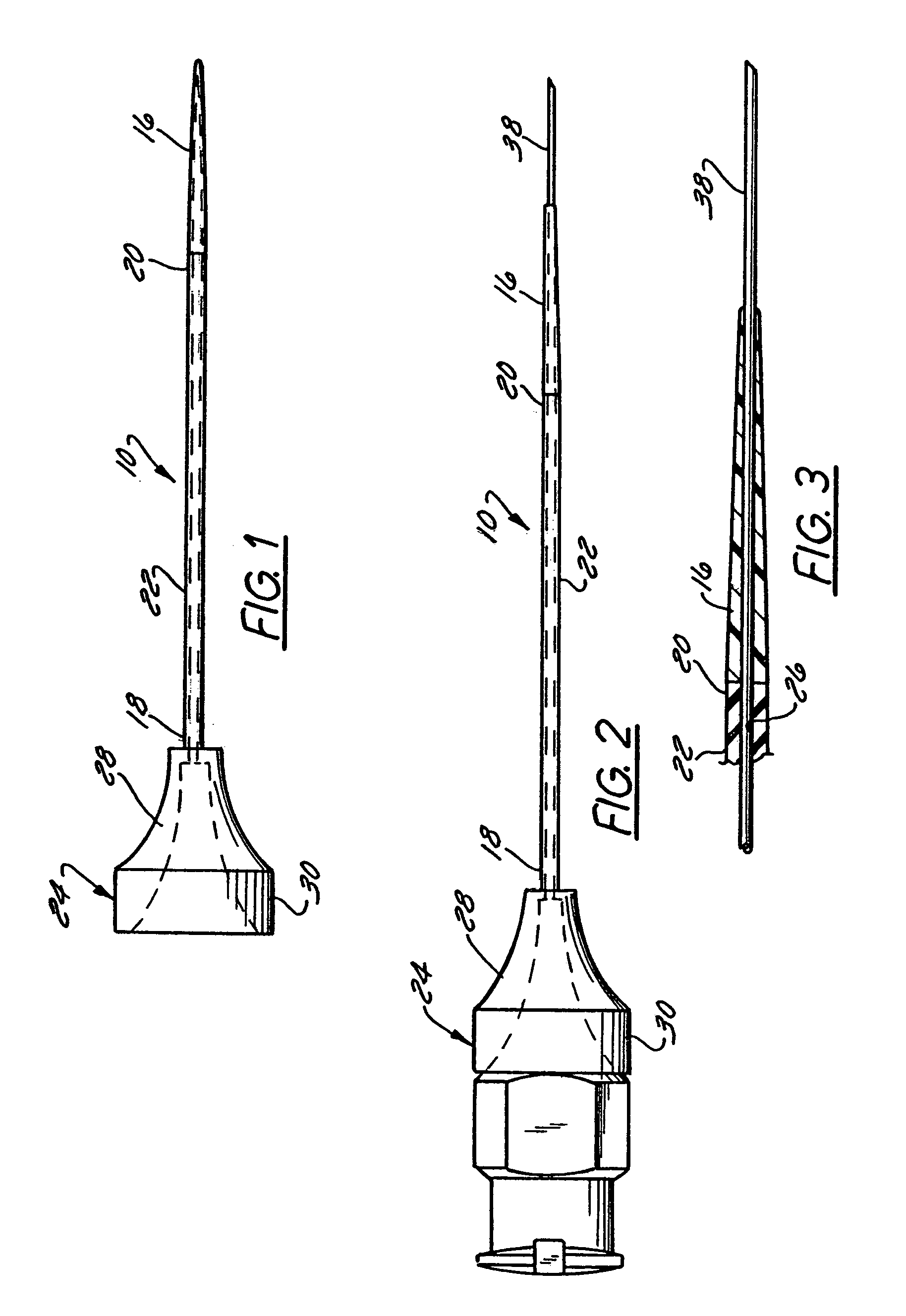
[0017]In a first preferred embodiment of the catheter introducer, the expandable tip is made from a material that becomes pliable based on temperature. At a lower temperature, such as room temperature, the tip material is rigid, and the tip can be threaded through a patient's venous or arterial system. Once inside the patient, the tip material becomes pliable as the patient's body temperature warms the material. The pliability allows for radial expansion of the tip such that the diameter of the opening of the tip can increase to accommodate insertion of devices having a range of O.D.s. Thus, at the higher temperature, a device with a larger O.D. than the I.D. of the tip of catheter introducer can be inserted through the opening of the pliable tip.
[0020]A method of using the catheter is also provided. In a preferred embodiment of the method, a guidewire or other device having a larger O.D. than an initial, unexpanded I.D. of a catheter tip is inserted through an opening in the catheter tip. This is accomplished by first cannulating a blood vessel with a needle. The catheter introducer described above is advanced over the needle. The relatively rigid, thin distal tip of the catheter introducer facilities insertion and minimizes discomfort and risk of injury to the patient during this insertion. The needle is then withdrawn, and a guidewire, dilator, or other device is inserted into the proximal end of the catheter introducer through the opening of the hub. The device is then axially extended through the lumen of the body and passed through the opening of the expandable tip to expand the opening and the surrounding tissue sufficiently to permit subsequent passage of the venous device. The catheter introducer is then withdrawn, and a catheter or other peripheral or central arterial or venous device is inserted through the passage in the patient's body and into the blood vessel over a guidewire that either is part of or constitutes the device previously inserted into the catheter introducer.
[0022]The catheter introducer described herein allows a device having a larger O.D. than the initial unexpanded I.D. of the catheter tip to be inserted through the opening of the catheter tip with a single needle stick. The catheter tip is made from a material that allows threading of the catheter through the patient's venous or arterial system without bunching. The material does not damage tissue of the patient. It also has a much smaller initial tip diameter than conventional catheter introducers. The catheter introducer described herein is of relatively simple construction, providing a lower cost of manufacture when compare to more complex designs.

Problems solved by technology

The construction of this catheter, however, is complex, and requires the formation of the spiral fold tip.
The construction of this catheter introducer is also complex.

Method used


Image

  • Catheter introducer having an expandable tip
  • Catheter introducer having an expandable tip
  • Catheter introducer having an expandable tip

Examples


first embodiment

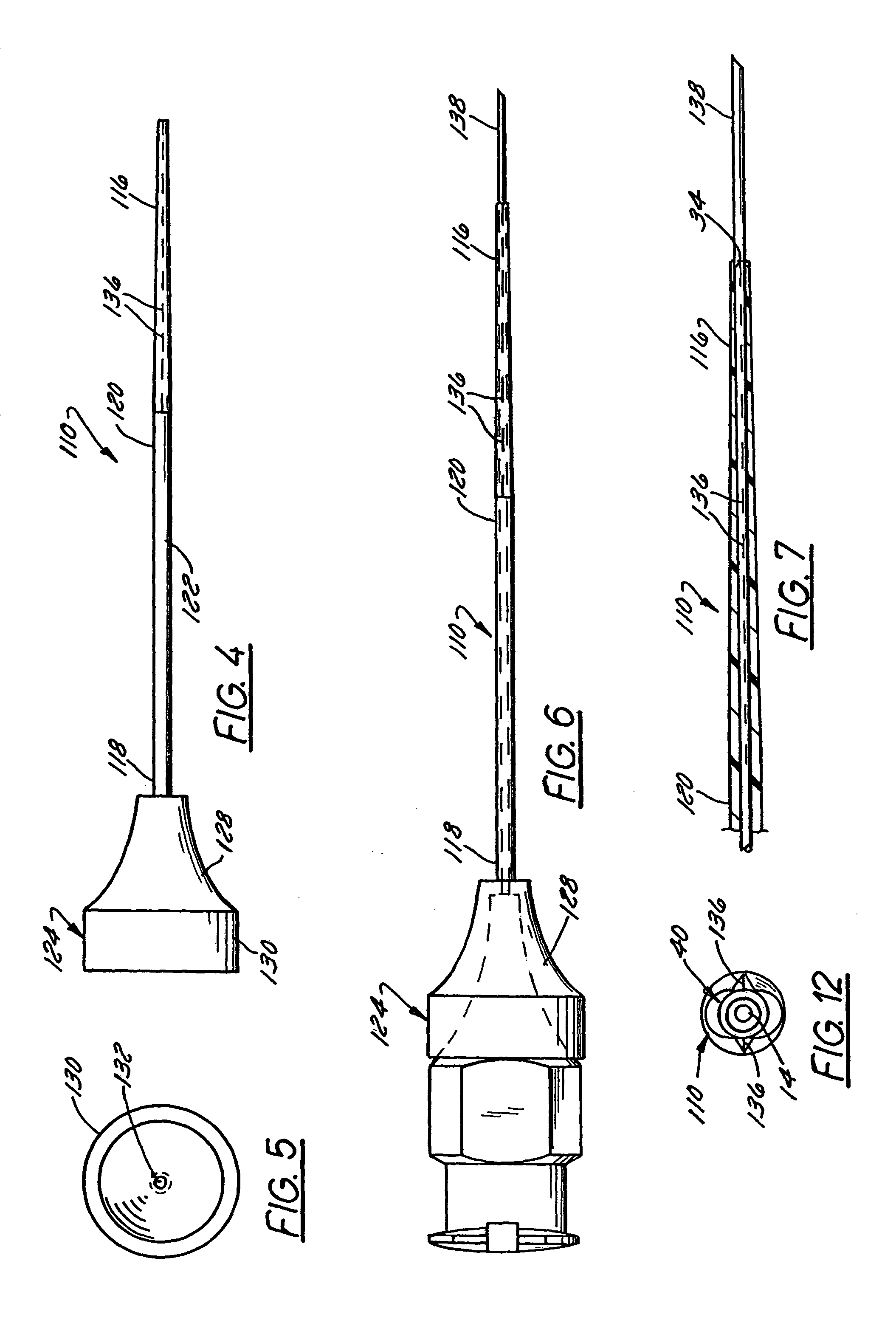
[0059]Referring now to FIGS. 4–7, a catheter introducer 110 is illustrated that differs from the catheter introducer 10 of the first embodiment primarily in that it has a different type of expandable tip 116. Elements of the catheter introducer 110 of FIGS. 4–7 corresponding to elements of the introducer 10 of FIGS. 1–3 are, accordingly, designated by the same reference numerals, incremented by 100. The introducer 110 therefore includes a body 122, a hub 124, and a tip 116.

[0060]In this preferred embodiment, the expandable catheter tip 116 is made of the same material as the catheter body 122, and the continuous and non-convoluted catheter tip 116 includes score lines 136 that extend partially or completely through the depth of the catheter tip 116. The material of the body and tip may, for example, comprise polytetrafluorethylene (PTFE), FEP, or PE. The score lines 136 weaken the structural integrity of the catheter tip 116 so as to permit the catheter tip 116 to expand or even spl...

second embodiment

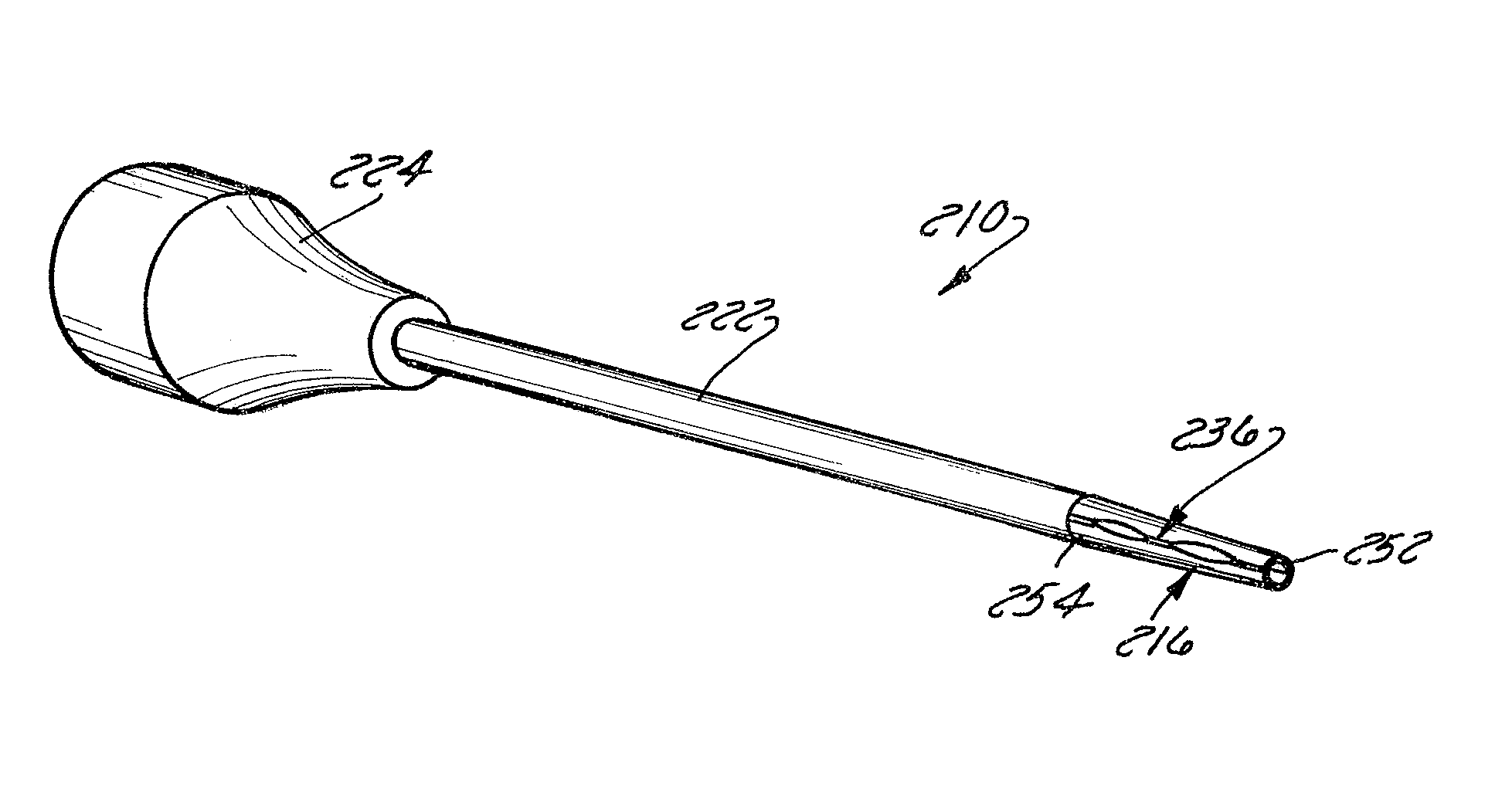
[0063]Referring now to FIGS. 13–20, a catheter introducer 210 is illustrated that differs from the catheter introducer 110 of the second embodiment primarily in that it has a different type of expandable tip 216. Elements of the catheter introducer 210 of FIGS. 13–20 corresponding to elements of the introducer 110 of FIGS. 4–7 are, accordingly, designated by the same reference numerals, incremented by 100. The introducer 210 therefore includes a body 222, a hub 224, and a tip 216. The tip 216 is about ½″ long and tapered as described above, preferably having a maximum inner diameter (ID) of about 0.04″ at its proximal end 254 and a minimum ID of about 0.031 at its distal end 252. The tip 216 also has one or more axially extending weakened portions 236 that split when a larger diameter object is threaded through the catheter introducer 210. The catheter introducer 210 preferably includes two weakened portions 236 offset by 180°, although other offsets are possible. In addition, less ...


PUM


Abstract

A catheter includes a body having an outer surface defining a lumen and an expandable tip on a distal end thereof. The tip includes an opening axially extending therethrough. Upon insertion of a device having a larger outer diameter than the inner diameter of the expandable tip, the opening permits passage of the device therethrough. The tip expands commensurately with a difference between the outer diameter of the device and the inner diameter of the expandable tip. The expandable tip includes a tubular wall having an axially extending weakened portion formed from (1) at least two axially aligned slit segments and (2) at least two axially aligned segments that are strengthened when compared to the slit segments. One of the strengthened segments is positioned between two of the slit segments. Another of the strengthened segments is formed between a distal-most slit segment and a distal end of the expandable tip.

Description

CROSS REFERENCE TO RELATED APPLICATION[0001]This application is a continuation-in-part of U.S. application Ser. No. 09 / 896,035; filed Jun. 29, 2001 now abandoned, that is entitled Catheter Introducer Having an Expandable Tip, the entire disclosure of which is incorporated herein by reference.FIELD OF THE INVENTION[0002]The invention relates to medical instruments, and in particular catheter introducers for introducing catheters and other medical devices into a patient's veins or arteries.DESCRIPTION OF THE RELATED ART[0003]Catheters are flexible tubes used for withdrawing fluids from or injecting fluids into a patient's body. For example, catheters can be used to introduce or withdraw fluids from a body cavity, duct, or vein, or artery (hereafter referred to as “blood vessels” for the sake of simplicity). They are used for a variety of purposes and for differing time periods.[0004]Short-term catheters are used for only a brief period of time, e.g., for a matter of hours or a day or ...

Claims


Application Information

Patent Timeline
IPC IPC(8): A61M5/178A61M25/06A61M29/00
CPCA61M25/0662A61M29/02A61M25/0074
Inventor KORKOR, ADEL B.ASH, STEPHENKRUGER, ROBERT J.
Owner A B KORKOR MEDICAL
Learn More