
Implantable coronary sinus lead and lead system

a technology of implantable leads and coronary sinuses, which is applied in the direction of internal electrodes, transvascular endocardial electrodes, therapy, etc., can solve the problems of inability to facilitate the distal end portion of the coronary sinus region to be positioned and manipulated, and the implantation of a lead in the coronary sinus region is often difficult, and achieves high flexibility.

Inactive Publication Date: 2005-11-22
PACESETTER INC
View PDF18 Cites 206 Cited by
  • Summary
  • Abstract
  • Description
  • Claims
  • Application Information

AI Technical Summary

Benefits of technology

[0016]Among other things, the invention provides a lead for left heart pacing and / or defibrillation which utilizes a soft, flexible material such as silicone rubber for the distal portion of the lead body and a stiffer material such as polyurethane for the proximal portion of the lead body. The use of such a composite design allows for a lead that is small in diameter throughout its length yet has a more desirable, more drivable stiffer proximal portion which is not prone to abrasion while at the same time providing a distal portion that is highly flexible for facilitating its placement in the coronary vessels overlying the left side of the heart.
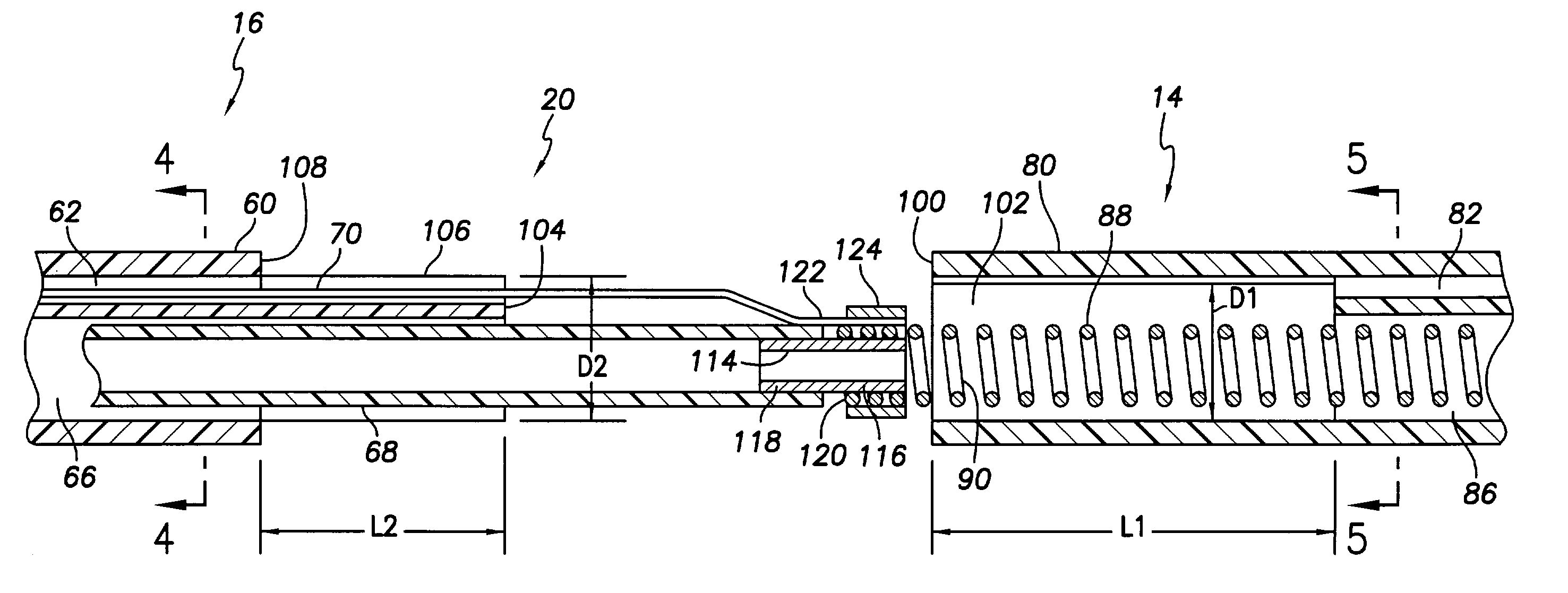
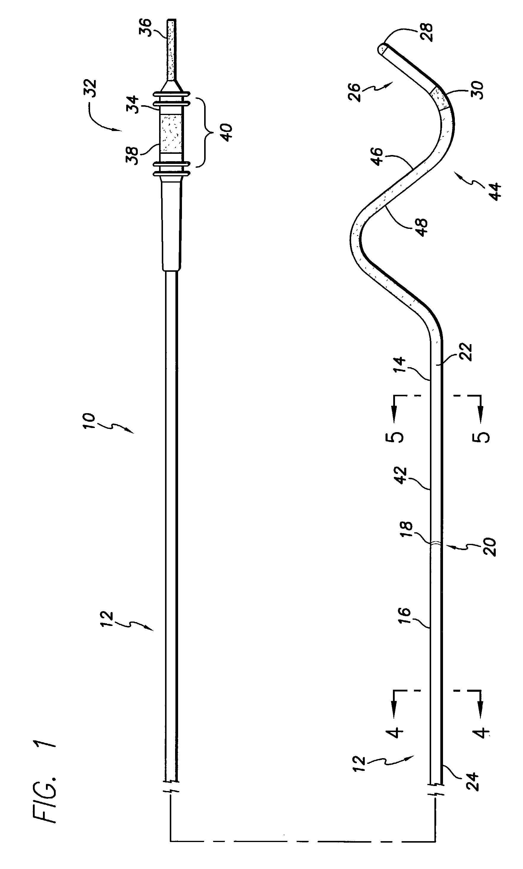
[0018]In accordance with another aspect of the invention, the preferred lengths of the distal and proximal portions of the lead body are such that when the lead body is implanted, the proximal portion / distal portion interface resides just distal of the coronary os so that a distal end of the stiffer proximal portion resides in the coronary sinus. Still further, the lead body may be isodiametric or the flexible distal portion of the lead body may have an outer diameter that is smaller than that of the stiffer proximal portion so as to facilitate access to narrow, distal coronary vessels.
[0019]Pursuant to yet another specific embodiment of the invention, the distal portion of the lead body may be configured to engage the wall of the coronary vessel in which the distal portion of the lead body is implanted to passively anchor the distal portion of the lead body in the coronary vessel. For example, the distal portion of the lead body may be configured with at least one S-shaped bend. Further, at least a portion of the outer surface of the distal portion of the lead body may be texturized to aid in passively anchoring the distal portion.
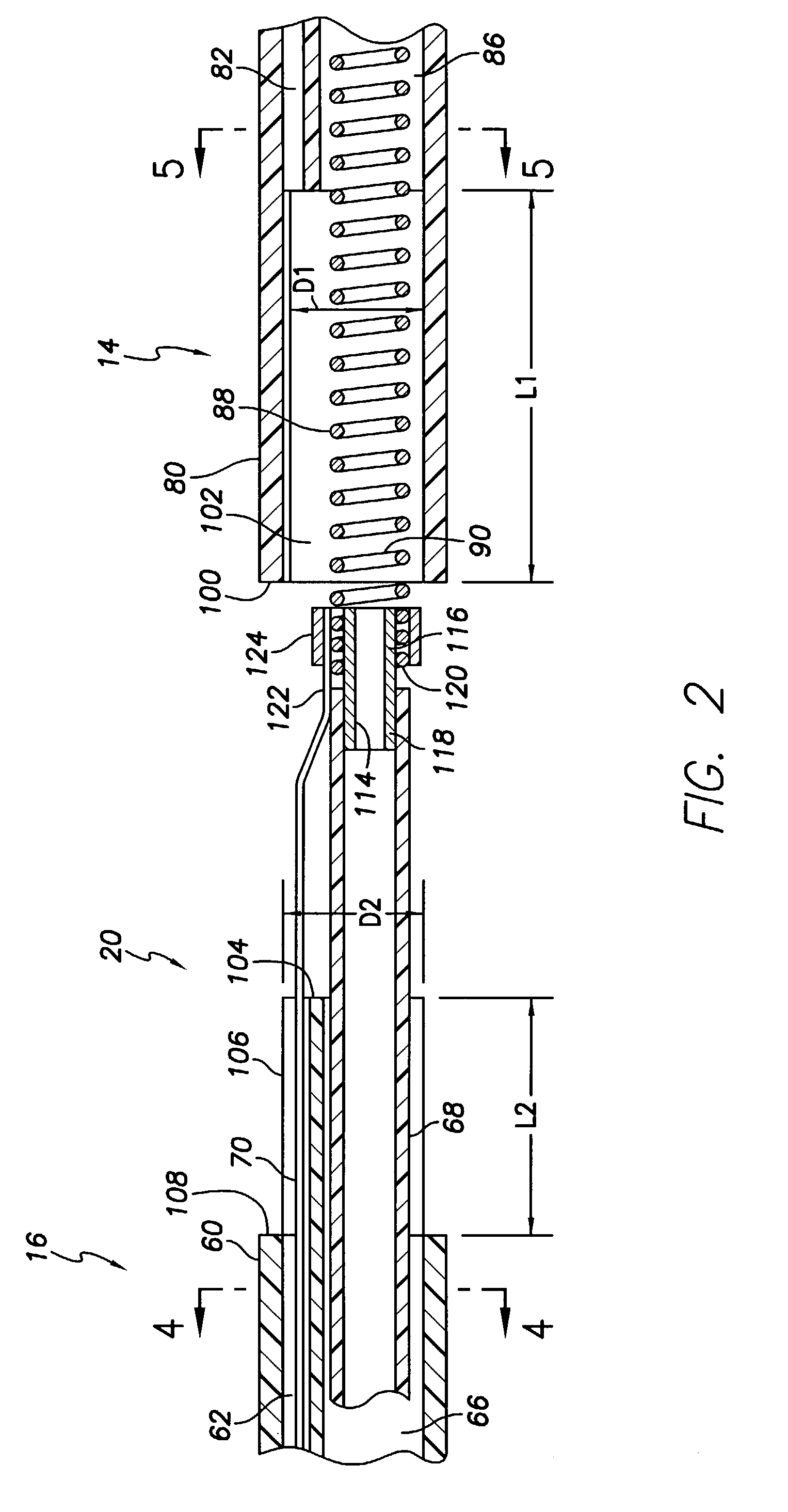
[0020]In accordance with another aspect of the invention, the relatively flexible distal portion of the lead body is coupled to the stiffer proximal portion by means of a robust joint that resists separation of the proximal and distal portions of the lead body. Pursuant to a preferred form of this aspect of the invention, the joint comprises telescoped sections of the distal and proximal portions of the lead body. More specifically, the telescoped sections of the distal and proximal portions of the lead body comprise a cored out section of the distal portion of the lead body and a reduced diameter section of the proximal portion of the lead body. Further, the cored out section of the distal portion of the lead body may have an inner diameter that is smaller than the outer diameter of the reduced diameter section of the proximal portion of the lead body so that an interference fit exists between the cored out and reduced diameter sections. Given these relative diameters, there will be a tendency for the telescoped sections to increasingly grip together if an attempt is made to pull apart the distal and proximal portions of the lead body. This “sphinctering” action further assures that the lead body portions will not separate when tension is applied to the proximal portion of the lead body during lead explantation.
[0021]Still further, the above-mentioned at least one conductor may comprise the series combination of a cable conductor residing in the proximal portion of the lead body and a more flexible coil conductor disposed within the distal portion of the lead body. The use of a flexible coil conductor in the distal portion of the lead body further facilitates left side placement of that portion.

Problems solved by technology

The implantation of a lead in the coronary sinus region is often difficult, however, because of the extreme curvatures in the coronary vessels, their narrowness, anomalies in the vascular anatomy because of disease, and the number of veins which may communicate with the desired lead feed path.
Although this approach works reasonably well the result of using just one insulation is that the insulation, if it is silicon rubber, is flexible but can be prone to abrasion.
On the other hand, where a typical, currently available biostable, biocompatible polyurethane is used to insulate the lead, and particularly the distal end portion thereof, the lead will be too stiff to permit ease of maneuvering of the distal end portion within the coronary vessels.
Leads which use both materials, with silicon rubber as the inner insulation and polyurethane as the outer insulation, have larger diameters and therefore are more difficult if not impossible to maneuver in the coronary venous system which, as indicated, has narrow veins with pronounced curvatures.
The patent does not disclose implantation of the pacing lead in the coronary veins on the left side of the heart; indeed, the lead diameter that is disclosed (about 2 mm) is too large to permit easy implantation of the lead deep into the coronary venous system.
In such a case, stylets often are not flexible enough to permit the lead to be implanted in the coronary vessels.

Method used


Image

  • Implantable coronary sinus lead and lead system
  • Implantable coronary sinus lead and lead system
  • Implantable coronary sinus lead and lead system

Examples


Embodiment Construction

[0043]The following description presents preferred embodiments of the invention representing the best mode contemplated for practicing the invention. This description is not to be taken in a limiting sense but is made merely for the purpose of describing the general principles of the invention whose scope is defined by the appended claims. Moreover, the context in which the invention is principally shown and described herein, that is, bipolar pacing and sensing leads, is illustrative only; it will be understood by those skilled in the art that the invention has applicability to a wide variety of body implantable lead types, including unipolar and multipolar leads for both pacing and sensing and optionally for providing cardioversion / defibrillation stimuli.

[0044]With reference to FIG. 1, there is shown a bipolar endocardial pacing and sensing lead 10 in accordance with a preferred embodiment of the present invention. The lead 10 includes a lead body 12 comprising a distal portion 14 ...


PUM


Abstract

An implantable stimulation lead is disclosed for placement in the coronary sinus region and its associated coronary vessels overlying the left side of a patient's heart. The lead comprises at least one proximal connector; at least one tissue stimulation electrode; at least one conductor coupled between the at least one proximal connector and the at least one stimulation electrode; and a lead body including a housing of insulating material enclosing the at least one conductor, the lead body having a relatively flexible distal portion of, for example, silicone rubber, having a length corresponding to the coronary sinus region of the heart, and a stiffer proximal portion of, for example, polyurethane. A robust transition joint comprising telescoped sections of the distal and proximal portions of the lead body couples the two portions of the lead body.Also provided is a versatile lead delivery system including a stylet stop disposed within the distal portion of the lead body. The stylet stop defines an aperture dimensioned to pass a guide wire but not the enlarged distal tip of a stylet. The lead includes a tip electrode having a longitudinally extending bore dimensioned to permit passage of the guide wire through the tip electrode.

Description

FIELD OF THE INVENTION[0001]The present invention relates generally to body implantable stimulation leads and lead systems. More particularly, the invention relates to body implantable stimulation leads designed to be placed intravenously in the coronary sinus region of the heart for left heart pacing, sensing and / or defibrillation, and to associated lead systems including devices for delivering such leads to target implantation sites.BACKGROUND OF THE INVENTION[0002]1. Left Side Stimulation and Sensing[0003]The advantages of providing pacing therapies to both the right and left heart chambers are well established. For example, in four chamber pacing systems, four pacing leads, typically bipolar leads, are positioned for both pacing and sensing in the respective heart chambers. To provide left side stimulation and sensing, leads are transvenously implanted in the coronary sinus region, for example, in a vein such as the great vein or the left posterior ventricular (LPV) vein or othe...

Claims


Application Information

Patent Timeline
Patent Type & Authority Patents(United States)
IPC IPC(8): A61N1/05
CPCA61N1/056A61N2001/0585
Inventor DOAN, PHONG D.MORGAN, KEVIN L.HELLAND, JOHN R.WILLIAMS, SHELDONSCHIMKE, KERWYNJENNEY, CHRISTOPHER R.
Owner PACESETTER INC
Learn More