Variable magnification optical system and image-taking apparatus

Inactive Publication Date: 2007-03-08
KONICA MINOLTA PHOTO IMAGING
View PDF0 Cites 12 Cited by
  • Summary
  • Abstract
  • Description
  • Claims
  • Application Information

AI Technical Summary

Benefits of technology

[0008] In view of the problem described above, the present invention has been made, and it is an object of the invention to provide a va

Problems solved by technology

However, in the DSC disclosed in patent publication 1, the use of the cylindrical lens i

Method used


Image

  • Variable magnification optical system and image-taking apparatus
  • Variable magnification optical system and image-taking apparatus
  • Variable magnification optical system and image-taking apparatus

Examples


first embodiment

[0029] The first embodiment of the present invention will be described below with reference to the accompanying drawings. For arrows provided to indicate directions in the figures, a mark “●” indicates the direction vertical to the paper surface.

[0030]

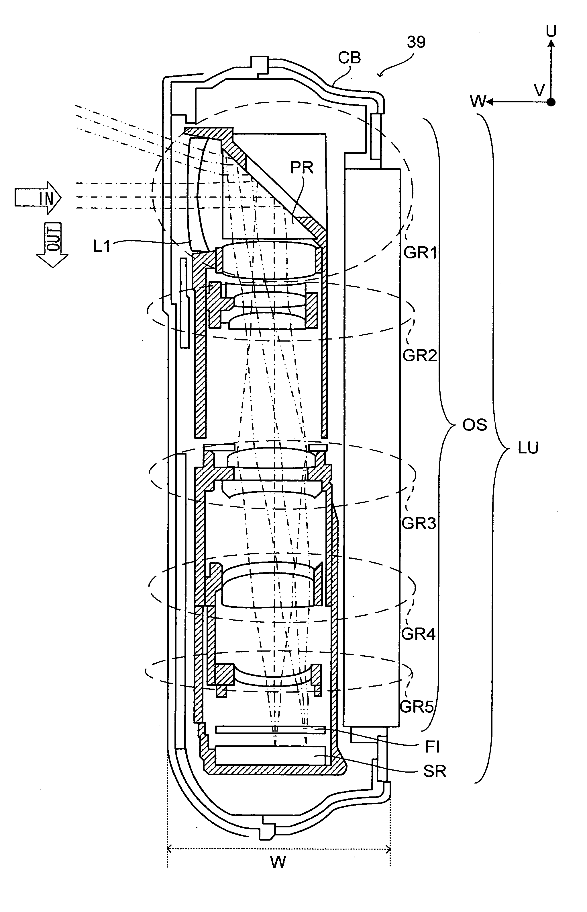
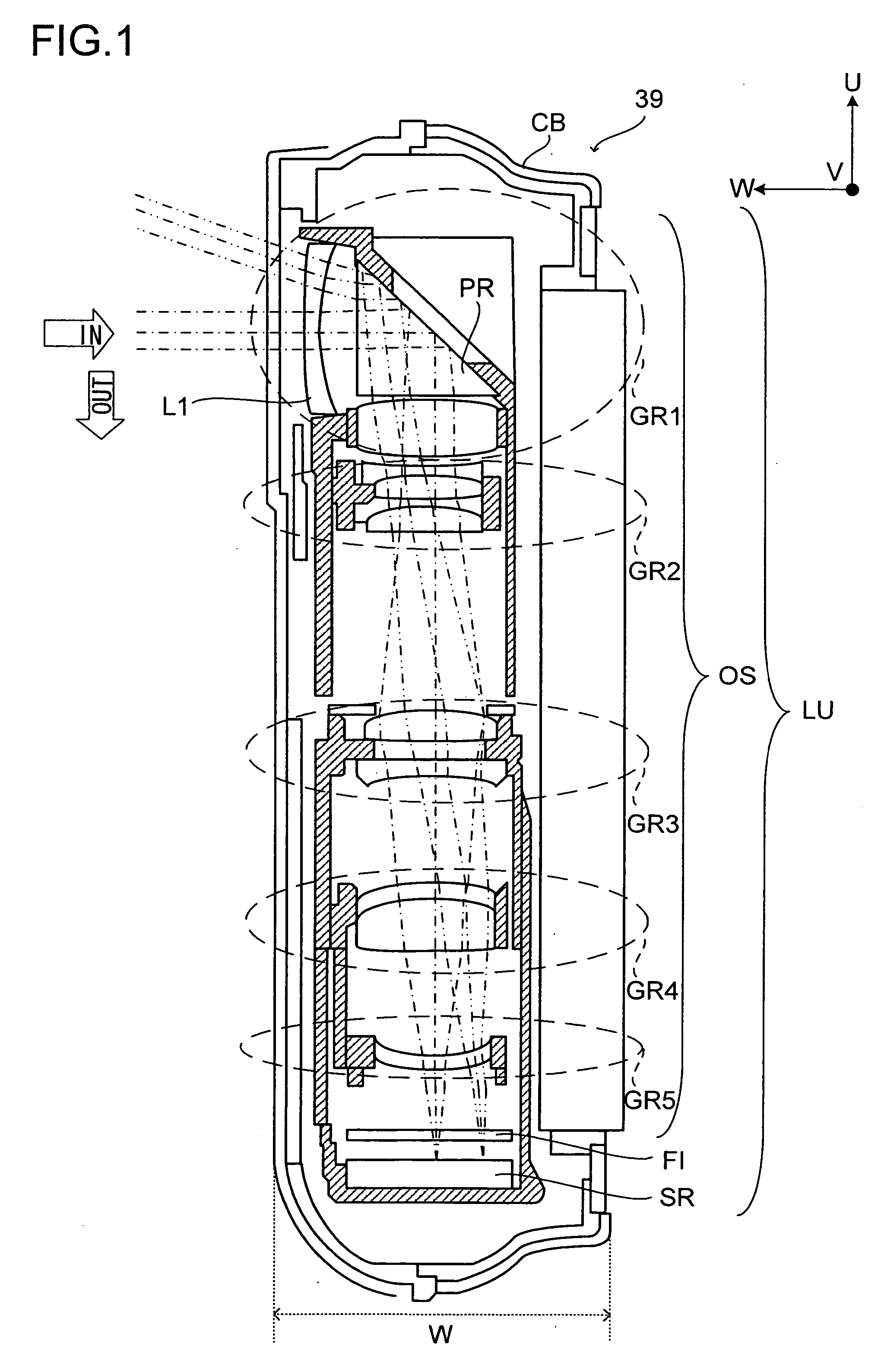
[0031]FIG. 9 shows the digital still camera (DSC) 39 as an example of an image-taking apparatus of the invention. FIGS. 10 to 12 show the front, rear, and side surfaces of the DSC 39, respectively, (together with a lens unit LU therein schematically shown as viewed from the side in FIG. 12). FIG. 13 shows the internal construction of the DSC 39. Note that U denotes the height direction of the DSC 39, V denotes the horizontal direction thereof, and W denotes the depth (width) direction thereof.

[0032] As shown in FIGS. 9 and 10, on the front surface of a camera body (main body portion) CB of the DSC 39 are provided at least: an opening 11 which permits the front surface of the lens unit LU (the lens element located on the most object s...

second embodiment

[0091] The second embodiment of the invention will be described below. Members having the same functions as those employed in the first embodiment are provided with the same numerals and thus are omitted from the description.

[0092] In the DSC 39 of the first embodiment, the control part 31 performs expansion processing on nonaxisymmetric image data to thereby convert it into axisymmetric image data. However, the present invention is not limited to this. That is, the DSC 39 of the invention is also capable of generating image data to be displayed on the LCD 15a or the like without performing expansion processing.

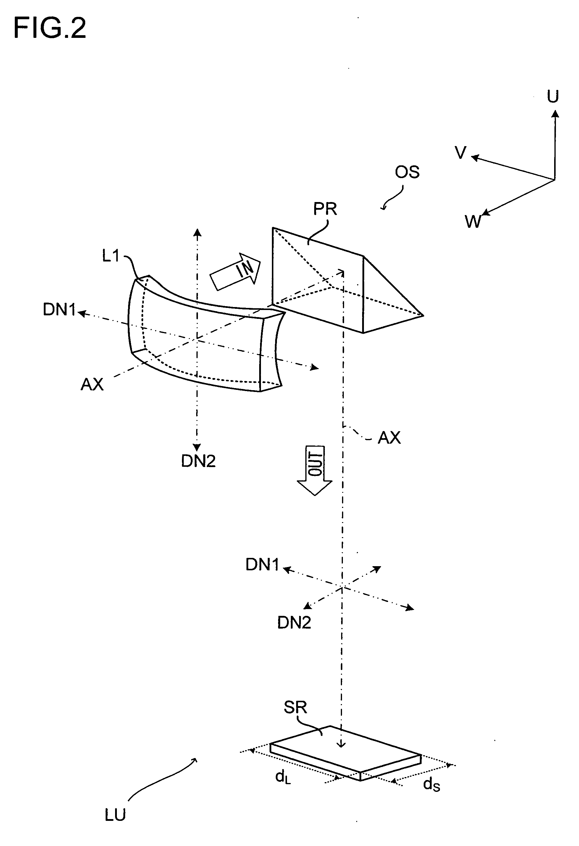
[0093] For example, as shown in FIG. 7, it is favorable that a second anamorphic lens element (second-type optical element) L2 be arranged closer to the image side than the anamorphic lens element (a first anamorphic lens element) L1 and the prism PR and also closer to the object side than the image sensor SR. This second anamorphic lens element L2 may be configured to alte...


PUM


Abstract

A variable magnification optical system includes: a plurality of lens groups for imaging a ray from the object side onto the light-receiving surface of an image sensor; and an optical prism for deflecting the optical path of the ray guided by these lens groups. The variable magnification optical system further includes an anamorphic lens element, which alters a beam of rays so that the beam becomes nonaxisymmetric to the optical axis.

Description

[0001] This application is based on Japanese Patent Application No. 2005-254372 filed on Sep. 2, 2005, the contents of which are hereby incorporated by reference. BACKGROUND OF THE INVENTION [0002] 1. Field of the Invention [0003] The present invention relates to a variable magnification optical system and an image-taking apparatus such as a digital still camera or the like. [0004] 2. Description of Related Art [0005] Following the wide spread use of personal computers (PC), digital still cameras (DSC) that can easily take in images have been wide spread in recent years. Thus, as is the case with cameras employing a sliver-film (silver salt cameras), there has been a demand for such digital cameras to be more multifunctional and downsized (slimmed-down). [0006] Examples of multifunctional apparatuses include a DSC (image-taking apparatus) that can photograph panorama images. For example, patent publication 1 to be described below discloses a DSC that is capable of obtaining from a s...

Claims


Application Information

Patent Timeline
IPC IPC(8): H04N5/225G02B13/16
CPCG02B13/08H04N5/2254G02B15/14G02B15/145H04N23/55
Inventor MATSUI, KAZUAKIHASHIMOTO, NAOKIMASHIMA, HIROSHIONISHI, HIDEO
Owner KONICA MINOLTA PHOTO IMAGING
Why Eureka
Try Eureka