Electromagnetic relay

a technology of electromagnetic relay and relay, applied in relays, circuit-breaking switches, protective switches, etc., can solve the problems of arc heat having a bad influence on surrounding parts, difficult to extinguish arc, and difficult to manage abnormalities

Active Publication Date: 2010-12-02
DENSO CORP
View PDF0 Cites 14 Cited by
  • Summary
  • Abstract
  • Description
  • Claims
  • Application Information

AI Technical Summary

Benefits of technology

[0016]The present invention has been made in view of such conventional problems, and thus, it is an object of the present invention to provide a small electromagnetic relay which enables interruption of current in all current value range.

Problems solved by technology

However, in case that the current which was flowing in the electromagnetic relay 9 before interrupted is a large current, it is difficult to extinguish the arc 8.
Moreover, if the arc 8 continues too long, the arc heat will have a bad influence on surrounding parts.
For this reason, there is a problem that it is difficult to manage the abnormality occurred while the current in this range flows.

Method used


Image

  • Electromagnetic relay
  • Electromagnetic relay
  • Electromagnetic relay

Examples


first embodiment

[0050]Hereinafter, an electromagnetic relay concerning an embodiment of the present invention will be described referring to FIG. 4-FIG. 11.

[0051]As shown in FIG. 4 and FIG. 5, the electromagnetic relay 1 of the present embodiment comprises a coil 2 which generates magnetic force when power is distributed, a contact point part 3 which is opened and closed by magnetic force, and a fuse functional part 4 which has a conductor wired electrically in series with the contact point part 3 and is disconnected when predetermined heat quantity is received.

[0052]The fuse functional part is disposed at a position which receives heat from an arc 8 (shown in FIG. 7) generated in the contact point part 3 when switching the contact point part 3 from conduction state (shown in FIG. 5) to cut-off state (shown in FIG. 4).

[0053]The electromagnetic relay 1 also comprises a pair of fixed holders 31 fixed to a main body 10 and holding a pair of fixed contact points 310, and a movable holder 32 holding in ...

second embodiment

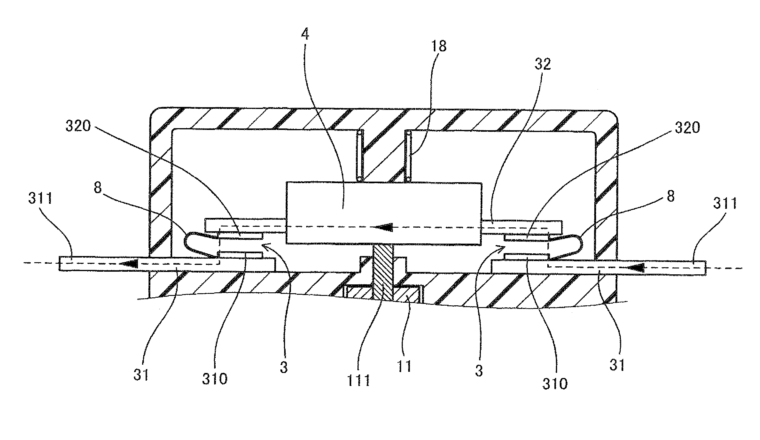
[0093]The present embodiment exemplifies the electromagnetic relay 1 in which the fuse functional part 4 constitutes a part of the fixed holder 31 as is shown in FIG. 12.

[0094]That is, the fuse functional part 4 is interposed between the fixed contact point 310 and the external terminal 311 in the fixed holder 31. Moreover, the fuse functional part 4 is disposed inside the cartridge case 103.

[0095]Other configuration is the same as that of the first embodiment.

[0096]In this embodiment also, the fuse functional part 4 can be provided in the position where arc heat is fully transmitted.

[0097]Other configuration has the same the operation effect as that of the first embodiment.

third embodiment

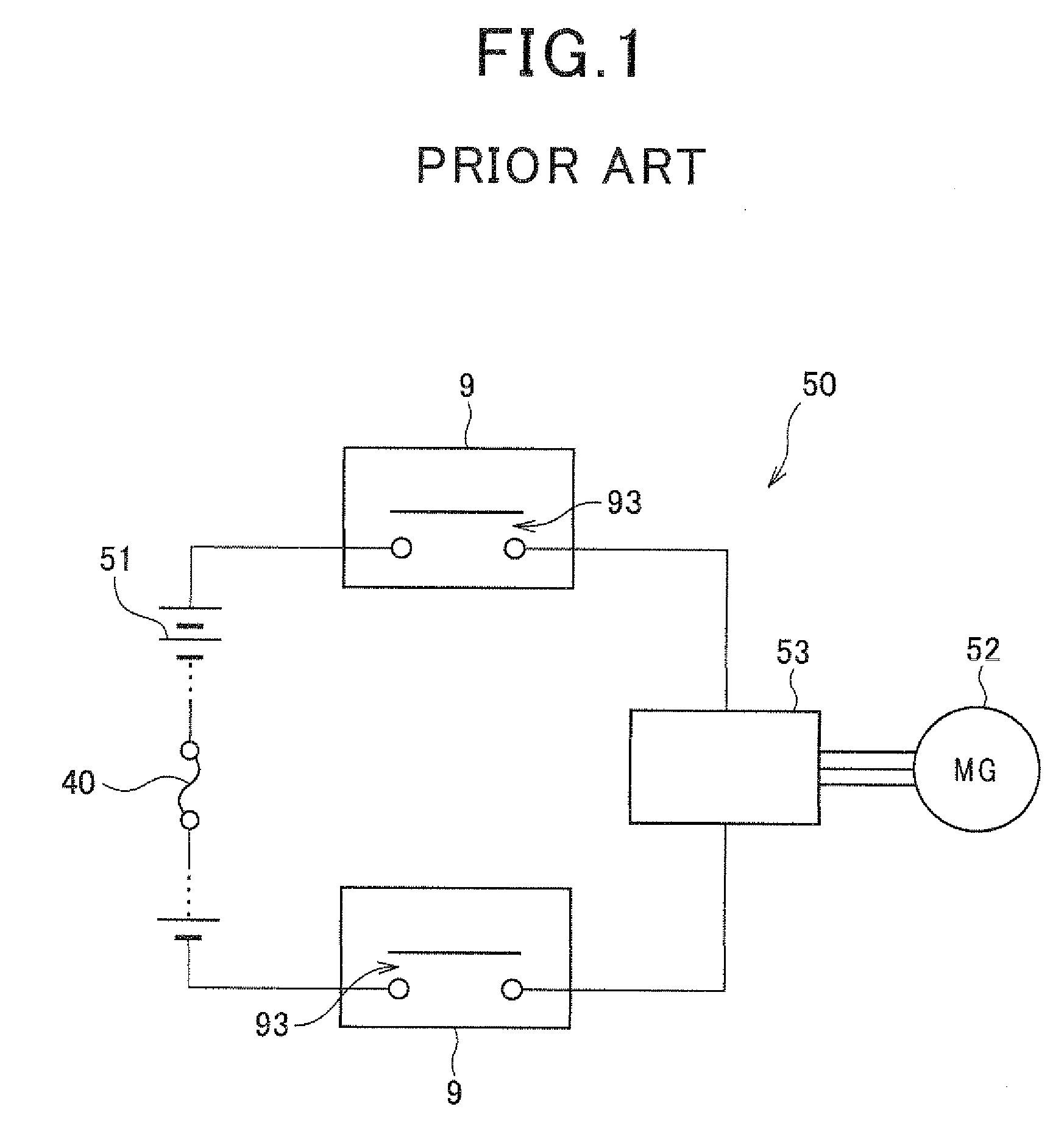
[0098]The present embodiment shows an example that the power circuit 5 incorporated in the electromagnetic relay 1 of the first embodiment as shown in FIG. 13.

[0099]That is, in the present embodiment, the high-voltage battery 51 incorporating the fuse functional part 40 is used.

[0100]Other features are the same as the case of the first embodiment.

[0101]In the present embodiment, the power circuit 5 is interrupted in the contact point part 3 of the electromagnetic relay 1, in the fuse functional part 4 incorporated in the electromagnetic relay 1, and three kinds of interruption parts of the fuse functional part 40 incorporated in the high-voltage battery 51.

[0102]Others have the same operation effect as those of the first embodiment.


PUM


Abstract

An electromagnetic relay comprises a coil generating magnetic force when power is distributed, a contact point part opened and closed by the magnetic force, and a fuse functional part having a conductor wired electrically in series with the contact point part and disconnected when predetermined heat quantity is received, and the fuse functional part is disposed at a position which receives arc heat generated in the contact point part when switching the contact point part from conduction state to cut-off state. Thereby, a small electromagnetic relay which enables interruption of current in all current value range can be provided.

Description

CROSS REFERENCES TO RELATED APPLICATION[0001]The present application relates to and incorporates by reference Japanese Patent application No. 2009-128442 filed on May 28, 2009.BACKGROUND OF THE INVENTION[0002]1. Field of the Invention[0003]The present invention relates to an electromagnetic relay which opens and closes a contact point part using magnetic force generated when power is distributed to a coil.[0004]2. Description of the Related Art[0005]As shown in FIG. 1, an electromagnetic relay 9 is incorporated in a power circuit 50 for switching a current flowing in a power circuit 50 in the conduction state or a cut-off state in order to drive a travelling motor in vehicle such as a hybrid vehicle, an electric vehicle etc. Moreover, a fuse functional part 40 which shuts off the current by disconnecting due to Joule heat when unusual large current flows is also incorporated in the power circuit 50.[0006]The electromagnetic relay 9 and the fuse functional part 40 are wired in series...

Claims


Application Information

Patent Timeline
Patent Type & Authority Applications(United States)
IPC IPC(8): H01H50/00
CPCH01H9/102H01H85/20H01H50/04
Inventor NAKAGAWA, EIJI
Owner DENSO CORP
Why Eureka
Try Eureka