Passive electronic fuse for protecting a DC application

a technology of electronic fuse and dc application, applied in the direction of electrical devices, transportation and packaging, and arrangements responsive to excess voltage, can solve the problems of manual replacement of fuses by operators, time-consuming, and loss of production, and achieve the effect of reducing production costs, reducing production costs, and reducing production costs

Active Publication Date: 2019-01-08
HITACHI ENERGY SWITZERLAND AG
View PDF11 Cites 0 Cited by
  • Summary
  • Abstract
  • Description
  • Claims
  • Application Information

AI Technical Summary

Benefits of technology

[0010]The object of the present invention is to provide an improved passive electronic fuse for a DC application. A first object of the invention is to provide a passive electronic fuse that interrupts the current based on physical properties of the components of the circuit in the event of a fault. A second object of the invention is to provide passive electronic fuse that can be reset in an easy manner. A third object of the invention is to provide passive electronic fuse that interrupts the current in a quick and reliable manner.

Problems solved by technology

A problem with the use of physical fuses is that the fuses must be manually replaced by an operator before the DC application can be operative after a fault.
This can however be time consuming.
Furthermore, replacing fuses adds cost to the DC application in form of personnel costs and loss of production due to unavailability of the system to which the DC application is used.
A problem with electronic fuses is that it takes relatively long time for the fuse to interrupt the current.
This may result in that an operator is subjected to harmful electric shock or damage to the DC application.

Method used


Image

  • Passive electronic fuse for protecting a DC application
  • Passive electronic fuse for protecting a DC application

Examples


first embodiment

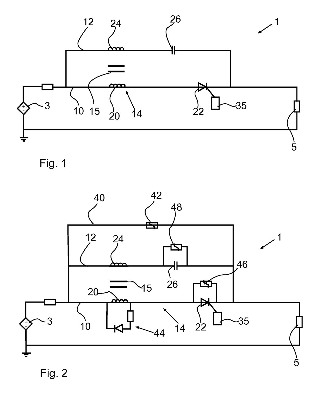
[0050]FIG. 1 shows an example of a passive electronic fuse 1 according to the invention. The electronic fuse 1 is adapted to be connected between the output of a DC energy source 3 and the load of a DC application 5. The DC energy source 3 may alternatively be a rectifier or similar non-constant DC source.

[0051]The electronic fuse 1 comprises a first leg 10 and a second leg 12 and a mutual inductor 14 between the first leg 10 and the second leg 12. The first leg 10 and the second leg 12 are connected in parallel.

[0052]The first leg 10 comprises a first winding 20 of the mutual inductor 14, and switch device in the form of a thyristor 22 or switch device with switching properties of a thyristor.

[0053]The second leg 12 comprises a second winding 24 of the mutual inductor 14, and a capacitor 26.

[0054]The mutual inductor 14 further comprises a core 15, such as an air core or a core of a magnetic material or a non-magnetic material.

[0055]The mutual inductor 14 is arranged so that a self-...

second embodiment

[0062]FIG. 2 shows an example of a passive electronic fuse 1 according to the invention.

[0063]The electronic fuse 1 differs from the first embodiment in that the electronic fuse 1 comprises a third leg 40 comprising an overvoltage protection circuit. The third leg 40 is connected in parallel to the first leg 10 and the second leg 12. The overvoltage protection circuit 40 comprises a first snubber 42.

[0064]The electronic fuse 1 further differs from the first embodiment in that the electronic fuse 1 comprises a second snubber 44, a third snubber 46, and a fourth snubber 48.

[0065]The second snubber 44 is connected in parallel to the first winding 20 of mutual inductor 14. The third snubber 46 is connected in parallel to the thyristor 22 of the first leg 10. The fourth snubber 48 is connected in parallel to the capacitor 26 of the second leg 12.

[0066]Any of the first snubber 42, the second snubber 44, the third snubber 46 and the fourth snubber 48 may be a varistor, a resistor capacitor...


PUM


Abstract

A passive electronic fuse for protecting a DC application in the event of a fault includes a first leg including a first winding of a mutual inductor and a switch device connected in series, a second leg including a second winding of the mutual inductor. The first leg and the second leg are connected in parallel and a self-inductance of the second winding is lower than a self-inductance of the first winding. The second leg further includes a capacitor connected in series with the second winding of the mutual inductor, and the switch device is a thyristor or a switch device with switching properties of a thyristor.

Description

FIELD OF THE INVENTION[0001]The present invention relates to a passive electronic fuse for protecting a DC application in the event of a fault. The electronic fuse is a passive circuit in that it relies on physical properties of the components of the circuit, and not on measurements and control means for protecting the DC application in the event of a fault. The DC application is for example DC breakers, electrical power system, such as charging units for a hybrid or pure electric vehicle, and electric energy storage systems, such as for data centers.[0002]The electronic fuse comprises a first leg comprising a first winding of a mutual inductor and a switch device connected in series, and a second leg comprising a second winding of the mutual inductor. The first leg and the second leg are connected in parallel and a self-inductance of the second winding is lower than a self-inductance of the first winding.[0003]The present invention also relates to an electrical power system for a h...

Claims


Application Information

Patent Timeline
Patent Type & Authority Patents(United States)
IPC IPC(8): H02H3/00H02H3/20H02H3/087H02H3/44B60L3/04H02H7/18H02H3/02
CPCH02H3/202B60L3/04H02H3/445H02H7/18H02H3/087H02H3/021
Inventor SAERS, ROBERTLILJESTRAND, LARSTENGNER, TOMASMAGNUSSON, JESPER
Owner HITACHI ENERGY SWITZERLAND AG
Why Eureka
Try Eureka