Fuel cell

a fuel cell and electrode technology, applied in the field of fuel cells, can solve the problems of not being able to maintain desired power generation performance, reactant gas not being uniformly supplied over the entire surface of the electrode, and not being able to achieve uniform output density per unit area in the entire fuel cell, so as to achieve the effect of improving the output density per unit area and simplifying the buffer structur

Inactive Publication Date: 2006-01-05
HONDA MOTOR CO LTD
View PDF6 Cites 14 Cited by
  • Summary
  • Abstract
  • Description
  • Claims
  • Application Information

AI Technical Summary

Benefits of technology

[0019] Thus, the buffer has a distribution function of the reactant gas in the reactant gas flow field, a distribution function of coolant in the coolant flow field. Thus, it is possible to simplify and downsize the buffer structure. The buffer has a substantially triangular shape. Each ...

Problems solved by technology

Therefore, the flow resistance varies in the inlet side channel 5a and the outlet side flow channels 5b, and thus, it is not possible to supply the reactant gas uniformly over the en...

Method used


Image

  • Fuel cell
  • Fuel cell
  • Fuel cell

Examples


Embodiment Construction

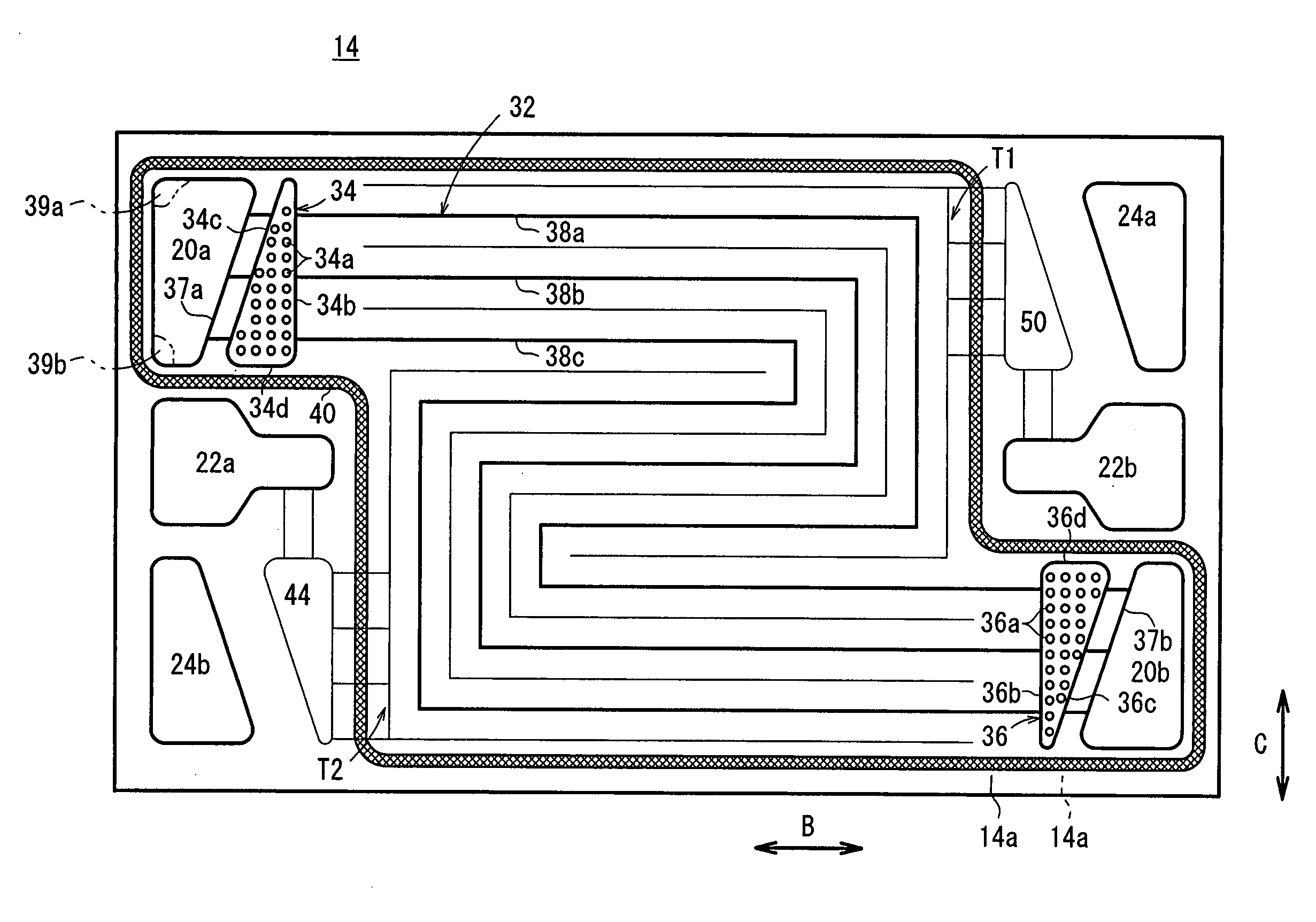
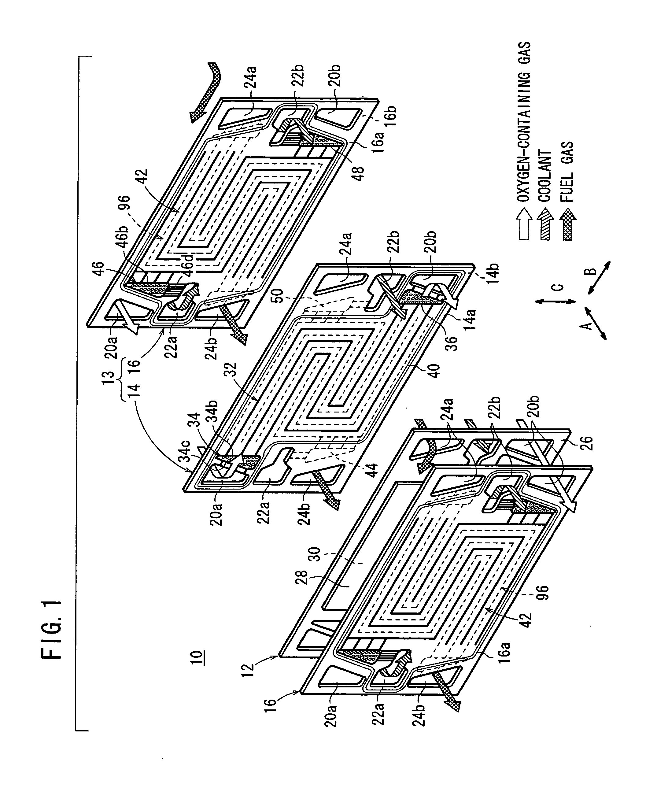
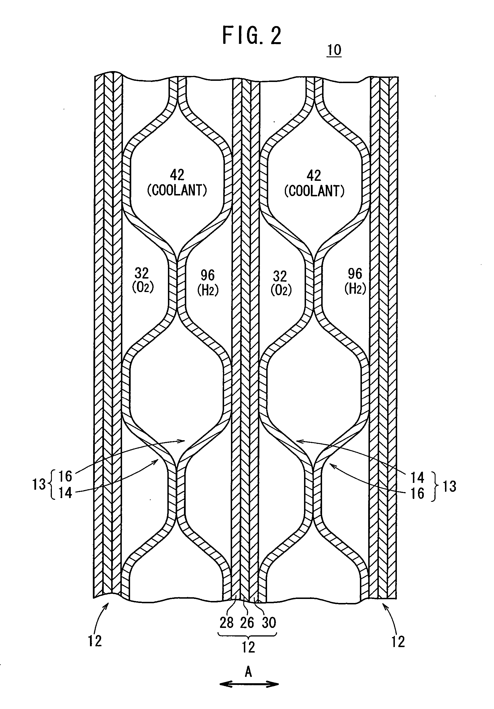
[0032]FIG. 1 is an exploded view showing main components of a fuel cell 10 according to an embodiment of the present invention. FIG. 2 is a cross sectional view showing a part of the fuel cell 10.

[0033] The fuel cell 10 is formed by stacking a membrane electrode assembly (electrolyte electrode assembly) 12 and separators (metal separators) 13 alternately. Each of the separators 13 includes first and second metal plates 14, 16, which are stacked together.

[0034] As shown in FIG. 1, at one end of the fuel cell 10 in a direction indicated by an arrow B, an oxygen-containing gas supply passage (reactant gas passage) 20a for supplying an oxidizing gas (reactant gas) such as an oxygen-containing gas, a coolant supply passage 22a for supplying a coolant, and a fuel gas discharge passage (reactant gas passage) 24b for discharging a fuel gas (reactant gas) such as a hydrogen-containing gas are arranged vertically in a direction indicated by an arrow C. The oxygen-containing gas supply passa...


PUM


Abstract

An oxygen-containing gas flow field for supplying an oxygen-containing gas from an oxygen-containing gas supply passage to an oxygen-containing gas discharge passage is formed on a first metal plate. The oxygen-containing gas flow field includes oxygen-containing gas flow grooves as serpentine flow grooves having two turn regions T1, T2. The oxygen-containing gas flow grooves have substantially the same length. The oxygen-containing gas flow grooves are connected to an inlet buffer and an outlet buffer at opposite ends. The inlet buffer and the outlet buffer have a substantially triangular shape, and are substantially symmetrical with each other.

Description

TECHNICAL FIELD [0001] The present invention relates to a fuel cell formed by alternately stacking an electrolyte electrode assembly and separators. The electrolyte electrode assembly includes a pair of electrodes and an electrolyte interposed between the electrodes. BACKGROUND ART [0002] For example, a solid polymer fuel cell employs a polymer ion exchange membrane as an electrolyte membrane. The electrolyte solid electrolyte membrane is interposed between an anode and a cathode to form a membrane electrode assembly (electrolyte electrode assembly). Each of the anode and the cathode is made of electrode catalyst and porous carbon. The membrane electrode assembly is sandwiched between separators (bipolar plates) to form the fuel cell. In use, generally, a predetermined number of the fuel cells are stacked together to form a fuel cell stack. [0003] In the fuel cell stack, a fuel gas (reactant gas) such as a gas chiefly containing hydrogen (hereinafter also referred to as the hydrogen...

Claims


Application Information

Patent Timeline
IPC IPC(8): H01M8/02H01M8/04H01M8/10
CPCH01M8/0206H01M8/0228H01M8/0247H01M8/0254H01M8/0258Y02E60/50H01M8/0263H01M8/0267H01M8/04074H01M8/242H01M2008/1095H01M8/026H01M8/2483H01M8/2457H01M8/0273
Inventor SUGIURA, SEIJIGOTO, SHUHEISASAMOTO, KAZUYASUGITA, NARUTOSHI
Owner HONDA MOTOR CO LTD
Why Eureka
Try Eureka