Liquid retainer, cooling and heating apparatus, and liquid transfer apparatus

a technology of liquid retainer and liquid retainer, which is applied in the direction of therapeutic cooling, contraceptive devices, therapeutic heating, etc., can solve the problems of complex structure of head cooling device, increased device cost, and large apparatus size, and achieves simple structure, improved comfort of head laid on liquid retainer, and suppression of pressure increase in pouch

Inactive Publication Date: 2013-05-16
LIGHT OPTICAL WORKS
View PDF3 Cites 3 Cited by
  • Summary
  • Abstract
  • Description
  • Claims
  • Application Information

AI Technical Summary

Benefits of technology

[0009]According to the present invention, the substantially flat-plate-like three-dimensional knit including the plurality of mesh-like knit garments and the plurality of chemical-fiber coupling strands for coupling the plurality of mesh-like knit garments to each other is arranged in the pouch having water blocking properties and flexibility. In this way, the liquid retainer is formed. Further, liquid is retained by the substantially flat-plate-like three-dimensional knit in the pouch. Thus, according to the present invention, with the use of the liquid retained by the substantially flat-plate-like three-dimensional knit in a simple structure using the substantially flat-plate-like three-dimensional knit and the pouch, a part of a human body, predetermined devices, and the like can be cooled and warmed.
[0010]Further, according to the present invention, the plurality of mesh-like knit garments are coupled to each other by the plurality of elastic chemical-fiber coupling strands. Thus, the liquid can be retained between the plurality of mesh-like knit garments with a predetermined retention force by utilizing surface tension of the liquid. Therefore, even when the liquid retainer is used while standing the pouch, the liquid can be retained between the plurality of mesh-like knit garments of the substantially flat-plate-like three-dimensional knit so that the liquid can be prevented from pooling on a lower side of the pouch. As a result, according to the present invention, even when the liquid retainer is used while standing the pouch, a cooling effect or a heating effect can be yielded in all the parts corresponding to the substantially flat-plate-like three-dimensional knit.
[0011]Still further, according to the present invention, the three-dimensional knit formed into the substantially flat-plate-like shape is arranged in the pouch. Thus, when the liquid retainer is used as a cooling pillow for cooling the head of a sleeper, the head laid on the liquid retainer can be supported with the plurality of elastic chemical-fiber coupling strands. Therefore, a pressure increase in the pouch can be suppressed by the plurality of elastic chemical-fiber coupling strands. Yet further, according to the present invention, the head laid on the liquid retainer can be supported with the plurality of elastic chemical-fiber coupling strands, and hence comfort to the head laid on the liquid retainer can be improved.
[0012]Yet further, according to the present invention, even when the liquid retainer is used while standing the pouch, the liquid can be retained between the plurality of mesh-like knit garments of the substantially flat-plate-like three-dimensional knit. Thus, with use of a liquid retainer including a pouch opened on one end side and another end side of the liquid retainer, it is possible to construct a liquid transfer apparatus for transferring liquid by utilizing the siphon principle from a supply source unit for the liquid in which one end side of the liquid retainer is immersed to a supply destination unit for the liquid in which another end side of the liquid retainer is immersed. Therefore, when the liquid retainer according to the present invention, which has the simple structure using the substantially flat-plate-like three-dimensional knit and the pouch, is used in the liquid transfer apparatus for transferring liquid by utilizing the siphon principle, the structure of the liquid transfer apparatus can be simplified and downsized.
[0013]As described above, according to the liquid retainer and the cooling and heating apparatus of the present invention, it is possible to cool and warm a part of a human body, predetermined devices, and the like with a simple structure. Further, when the liquid retainer of the present invention is used for the liquid transfer apparatus for transferring liquid by utilizing the siphon principle, it is possible to simplify and downsize the structure of the liquid transfer apparatus.

Problems solved by technology

In this way, the structure of the head cooling device is complicated, and hence cost of the device may increase.
In this way, the structure of the liquid transfer apparatus is complicated, and hence there is a disadvantage that the apparatus is large in size.

Method used


Image

  • Liquid retainer, cooling and heating apparatus, and liquid transfer apparatus
  • Liquid retainer, cooling and heating apparatus, and liquid transfer apparatus
  • Liquid retainer, cooling and heating apparatus, and liquid transfer apparatus

Examples


first embodiment

[0027](Schematic Structure of Cooling and Heating Apparatus)

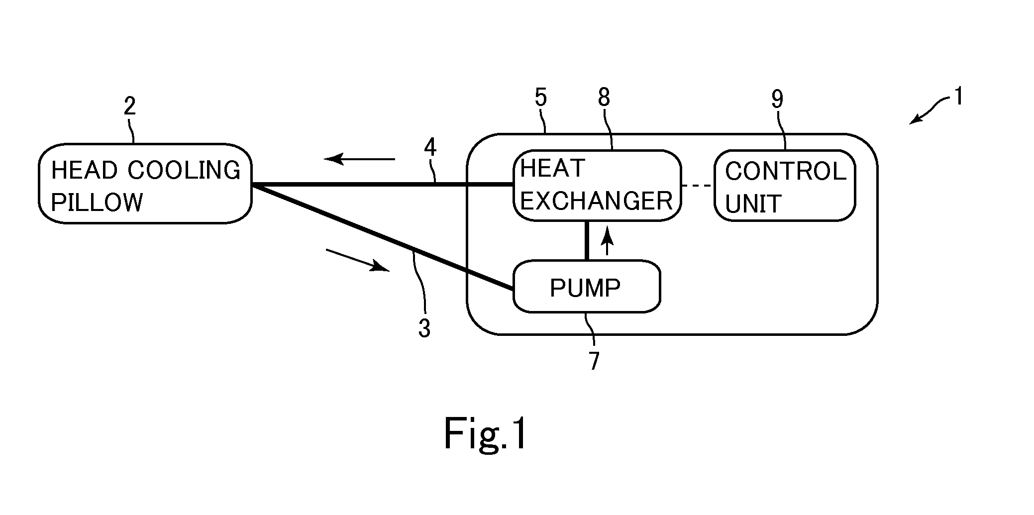
[0028]FIG. 1 is a block diagram of a schematic structure of a cooling and heating apparatus 1 according to an embodiment of the present invention.

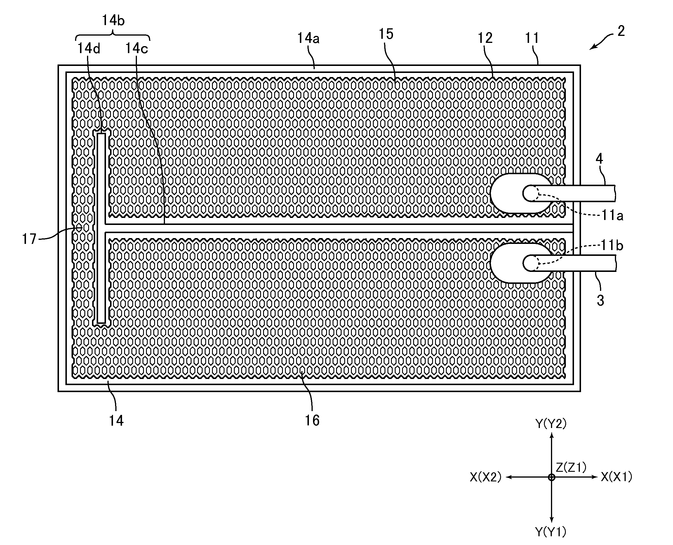
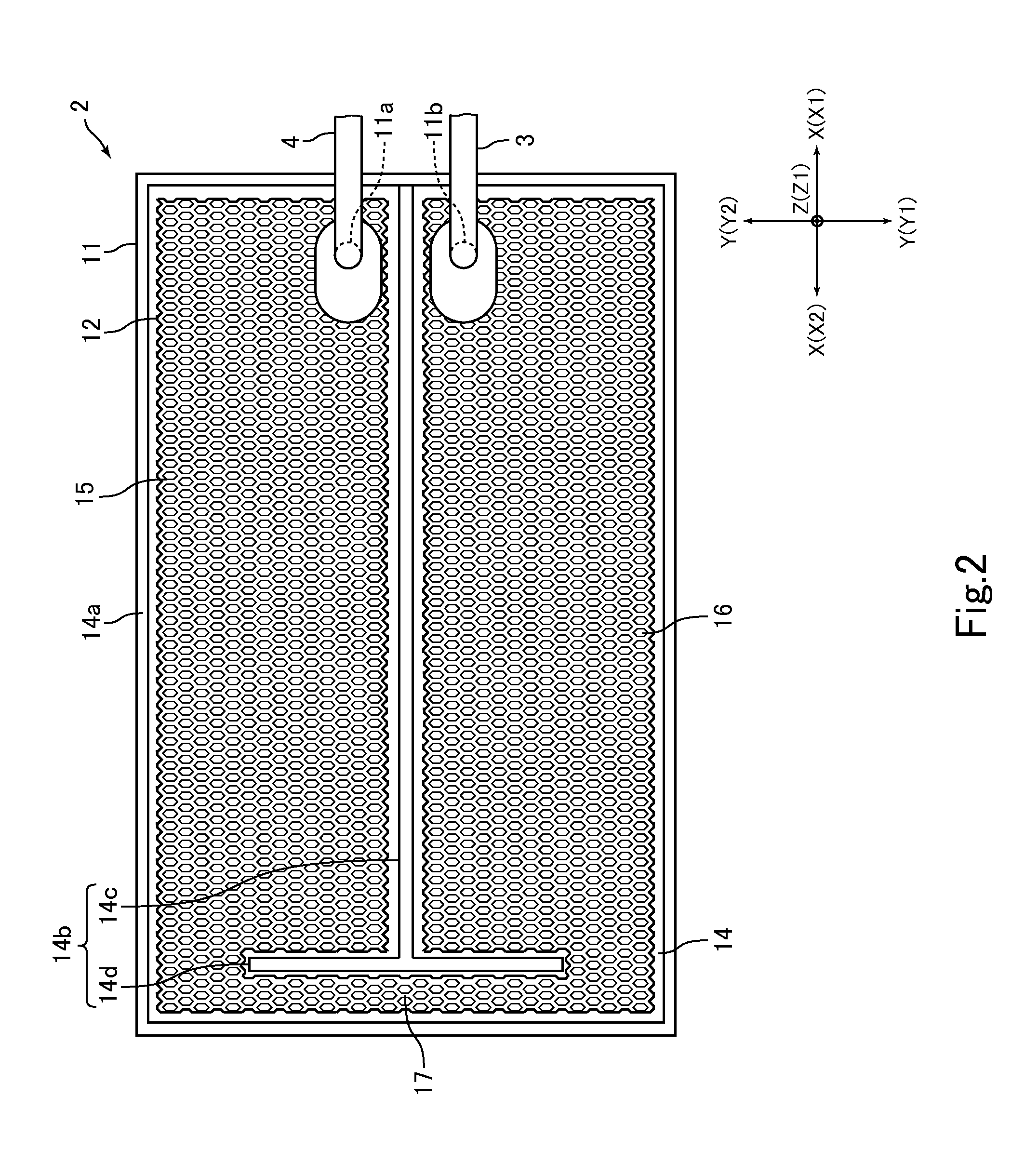
[0029]The cooling and heating apparatus 1 according to this embodiment is a head cooling apparatus for cooling the head of a sleeping user. Therefore, in the following, the cooling and heating apparatus 1 according to this embodiment is also referred to as “head cooling apparatus 1.” For example, the head cooling apparatus 1 is used while being set to beds in hospitals, nursing homes, and the like. As illustrated in FIG. 1, the head cooling apparatus 1 includes ahead cooling pillow 2 (hereinafter abbreviated as “pillow 2”) as a liquid retainer on which the user's head is laid, and a mechanical unit 5 connected to the pillow 2 through intermediation of flexible tubes 3 and 4. Cooling liquid circulates between the pillow 2 and the mechanical unit 5. In this embodiment, the cooling l...

second embodiment

[0091]FIGS. 12A and 12B are schematic views of a liquid transfer apparatus 91 according to an embodiment of the present invention. Specifically, FIG. 12A is a schematic side view of the liquid transfer apparatus 91, and FIG. 12B is a view of a liquid transfer tool 92 and a liquid supply source container 93 viewed in a direction of arrows E-E in FIG. 12A.

[0092]The liquid transfer apparatus 91 according to this embodiment is an apparatus for transferring liquid by utilizing a siphon principle. The liquid transferred by the liquid transfer apparatus 91 includes ink for ink jet printers. In this case, the liquid transfer apparatus 91 is used while being mounted to the ink jet printer. Further, the liquid transferred by the liquid transfer apparatus 91 includes fertilizer (liquid fertilizer), solvents, oil, chemicals, medicines, blood, or blood isolates. In those cases, the liquid transfer apparatus 91 is used while being mounted to various apparatuses and devices.

[0093]The liquid transf...


PUM


Abstract

Provided is a liquid retainer having a simple structure capable of cooling and warming a part of a human body, predetermined devices, and the like. A liquid retainer includes: a pouch having water blocking properties and flexibility and formed into a pouch shape; and a three-dimensional knit including: a plurality of mesh-like knit garments arranged substantially parallel to each other; and a plurality of coupling strands for coupling the plurality of mesh-like knit garments to each other. The plurality of coupling strands of the three-dimensional knit are made of elastic chemical fiber. The three-dimensional knit is formed into a substantially flat-plate-like shape and arranged in the pouch. Further, the three-dimensional knit retains liquid in the pouch.

Description

CROSS-REFERENCE TO RELATED APPLICATIONS[0001]This application claims priority to Japanese Application No. 2011-250270 filed Nov. 16, 2011 and Japanese Application No. 2012-098609 filed Apr. 24, 2012, the entire disclosures of which are hereby incorporated by reference.FIELD OF THE INVENTION[0002]The present invention relates to a liquid retainer capable of holding liquid therein. Further, the present invention also relates to a cooling and heating apparatus and a liquid transfer apparatus each including the liquid retainer.BACKGROUND OF THE INVENTION[0003]Conventionally, there has been proposed a helmet-like head cooling device for cooling the head of a patient (for example, refer to Japanese Patent Application Laid-open No. 2001-258924). The head cooling device described in Japanese Patent Application Laid-open No. 2001-258924 includes a plurality of tubular cooling bags arranged in parallel to one another, a cooling water supply bag connected to one end of each of the tubular cool...

Claims


Application Information

Patent Timeline
Patent Type & Authority Applications(United States)
IPC IPC(8): A61F7/00
CPCA61F7/0085A61F7/02A61F2007/026A61F2007/0054A61F2007/0228A61F2007/0002
Inventor IWANAMI, MASATOMIURAI, KATSUJI
Owner LIGHT OPTICAL WORKS
Why Eureka
Try Eureka