
System for determining number of particles

a particle and system technology, applied in the field of can solve the problems of increasing the number of components, the bulkyness of the system for determining particle number, and the difficulty of the filter mass method in determining the amount in view of accuracy, so as to simplify and reduce the structure of the system, the effect of reducing the cos

Active Publication Date: 2014-08-05
HORIBA LTD
View PDF43 Cites 1 Cited by
  • Summary
  • Abstract
  • Description
  • Claims
  • Application Information

AI Technical Summary

Benefits of technology

[0017]In accordance with the invention having the arrangement, it is possible to simplify and downsize a structure of the system for determining a number of particles and to reduce its cost.

Problems solved by technology

However, since the exhausted amount of the particulate matters has been subtle, it becomes difficult for the filter mass method to measure the amount in view of the accuracy.
However, if the orifice part, the pressure sensor for measuring the differential pressure, the pressure sensor for measuring the absolute pressure and a temperature adjustor are arranged in the upstream side of the diluter, there are not only a problem that the system for determining the number of particles becomes bulky but also a problem that a number of components increases so as to increase its cost.
However, since this arrangement uses the mass flow controller, there are problems such that not only the system for determining a number of particles becomes bulky but also its cost increases.

Method used


Image

  • System for determining number of particles
  • System for determining number of particles
  • System for determining number of particles

Examples


Embodiment Construction

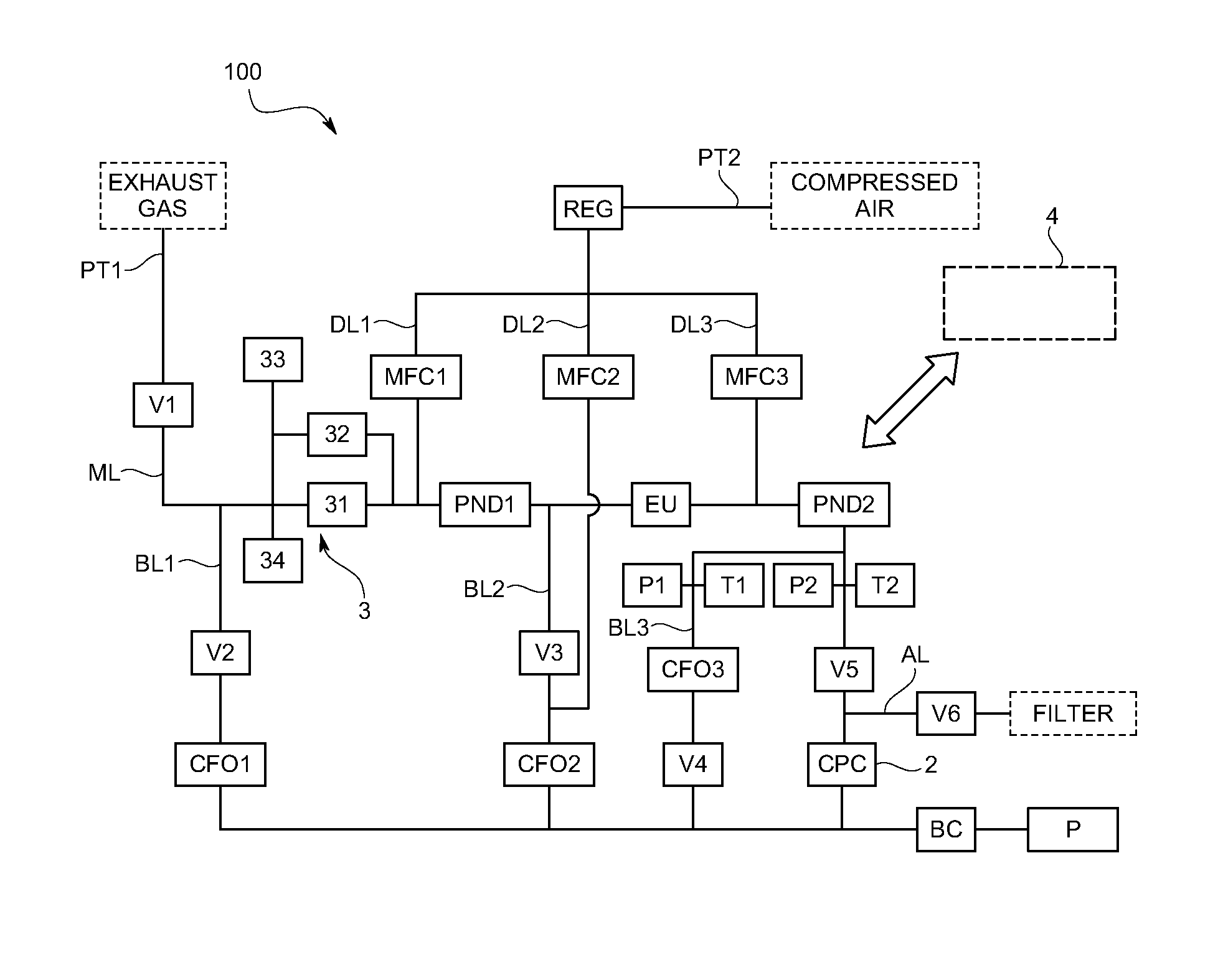
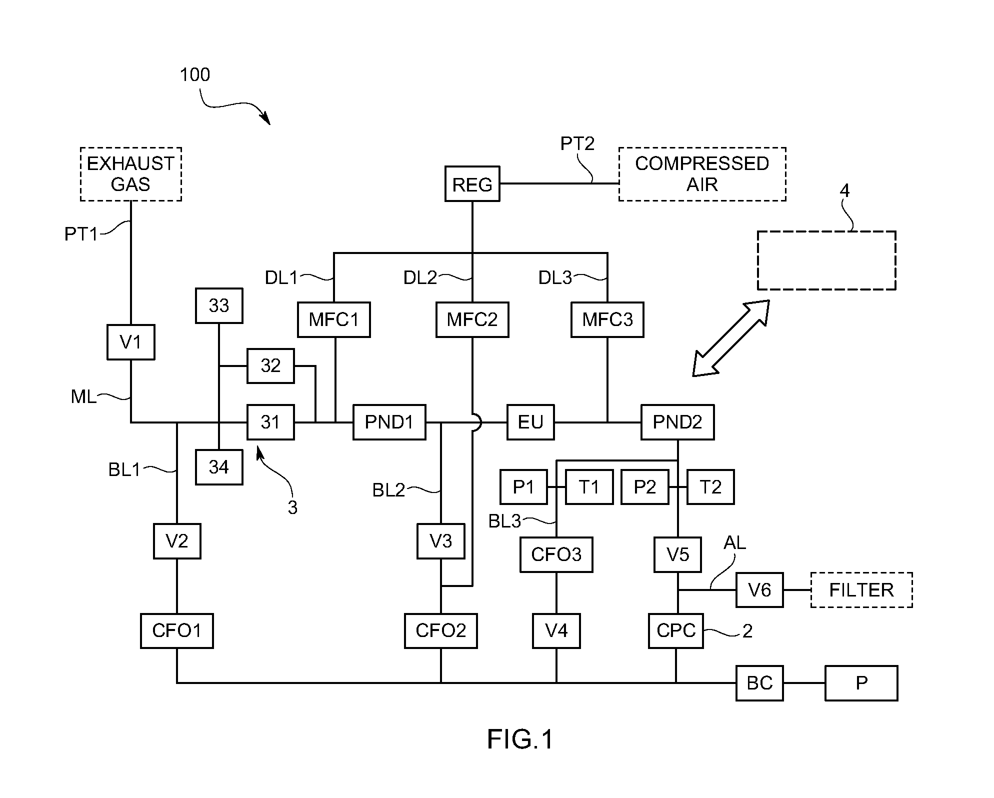
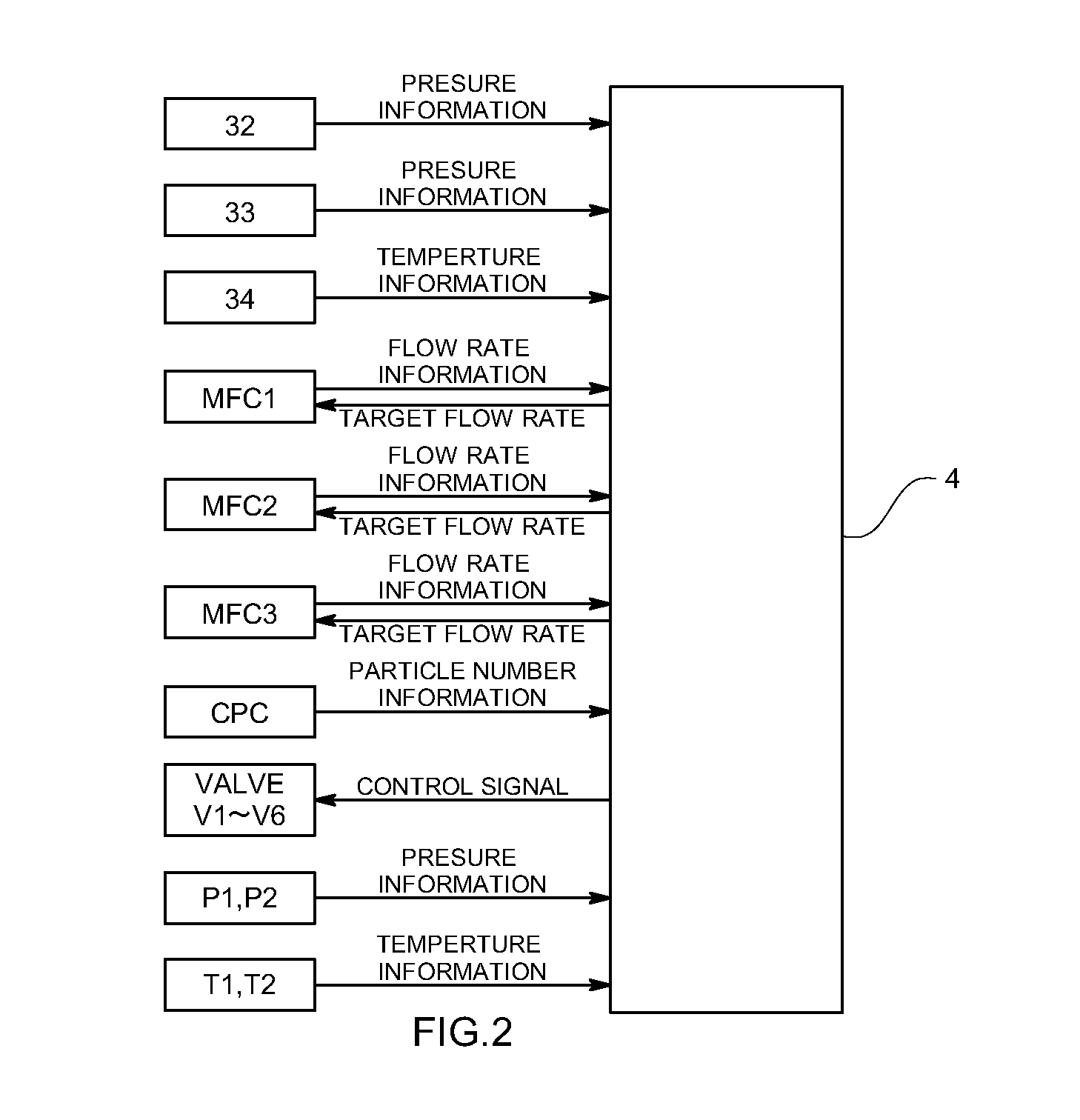
[0044]One embodiment of a system for determining a number of particles in accordance with this invention will be explained with reference to drawings.

[0045]The system for determining the number of particles (100) in accordance with this embodiment introduces an exhaust gas of an engine into a main flow channel (ML) arranged inside through an exhaust gas introduction port (PT1), dilutes or evaporates the introduced exhaust gas, and measures particulate matters (PM) as being solid particles in the exhaust gas by means of a particle number measuring unit (2) arranged in the main flow channel (ML).

[0046]The exhaust gas introduction port (PT1) is connected to an exhaust gas line from an engine, not shown in drawings, and is so arranged to introduce, for example, the exhaust gas directly from the engine or the exhaust gas diluted by a whole flow dilution tunnel or a diverted flow dilution tunnel into the exhaust gas introduction port (PT1). The exhaust gas hereinafter called as the exhaus...


PUM

PropertyMeasurementUnit
diameteraaaaaaaaaa
particle diameteraaaaaaaaaa

Abstract

A system for determining a number of particles includes a diluter arranged at a connecting point of a main flow channel and dilution gas flow channel, a dilution gas flow rate control part that controls the flow rate of the dilution gas introduced into the diluter, a particle number measuring unit that measures a number of solid particles in a diluted exhaust gas, a bypass flow channel that bifurcates from between the diluter and particle number measuring unit in the main flow channel and in which a constant flow rate unit is arranged, and an information processing unit that calculates the dilution factor of the exhaust gas based on a dilution gas flow rate controlled by the dilution gas flow rate control part, and a total of a unit flow rate of the particle number measuring unit and a set flow rate of the constant flow rate unit.

Description

FIELD OF THE ART[0001]This invention relates to a system for determining number of particles that measures a number of solid particles such as particulate matters (PM) contained in en exhaust gas of an engine.BACKGROUND ART[0002]As a method for measuring particulate matters (PM) as being one of exhausted materials from an engine well known is a filter mass method that collects particulate matters by the use of a filter and measures a mass of the particulate matters. However, since the exhausted amount of the particulate matters has been subtle, it becomes difficult for the filter mass method to measure the amount in view of the accuracy. Under this condition, as its alternative method developed is a method for measuring a number of the particulate matters in the exhaust gas. A concrete system structure is known that a diluter to dilute the exhaust gas of the engine with air or the like is arranged upstream of a particle number measuring unit, and a part of the diluted exhaust gas is...

Claims


Application Information

Patent Timeline
Patent Type & Authority Patents(United States)
IPC IPC(8): G01N7/00
CPCG01N1/2252G01N2001/2264G01N2015/0675
Inventor MATSUYAMA, TAKASHISHINOHARA, MASAYOSHIOTSUKI, YOSHINORIOKADA, KAORUAKITA, MASANOBU
Owner HORIBA LTD
Learn More