Permanent magnetic rotating machine

a permanent magnet, rotating machine technology, applied in the direction of dynamo-electric machines, magnetic circuit rotating parts, magnetic circuit shape/form/construction, etc., can solve the problems of insufficient reduction of cogging torque, insufficient conditions, and more heat generation, so as to reduce the cogging torque

Active Publication Date: 2005-01-20
MITSUBISHI ELECTRIC CORP
View PDF6 Cites 11 Cited by
  • Summary
  • Abstract
  • Description
  • Claims
  • Application Information

AI Technical Summary

Benefits of technology

When the theoretical skew angle θs (electrical angle) is theoretically decided in the above way, and applied to the actual rotating machine, reduction of the cogging torque may be still insufficie...

Problems solved by technology

When the theoretical skew angle θs (electrical angle) is theoretically decided in the above way, and applied to the actual rotating machine, reduction of the cogging torque may be still insufficient.
But if the electric loading is increased, more heat is...

Method used


Image

  • Permanent magnetic rotating machine
  • Permanent magnetic rotating machine
  • Permanent magnetic rotating machine

Examples


embodiment 1

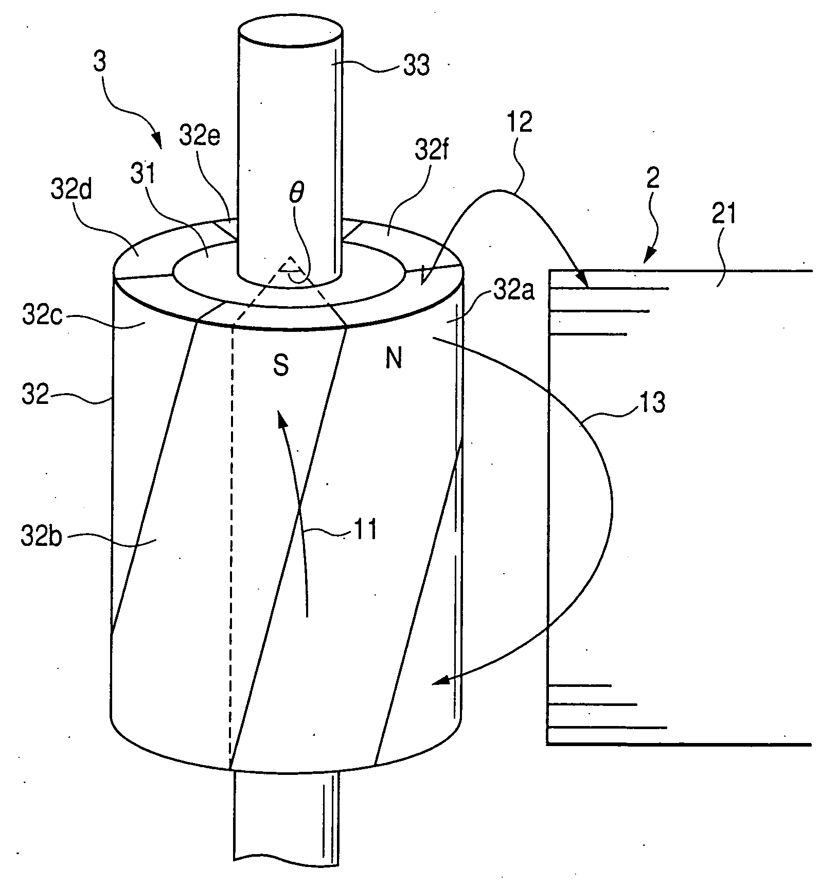
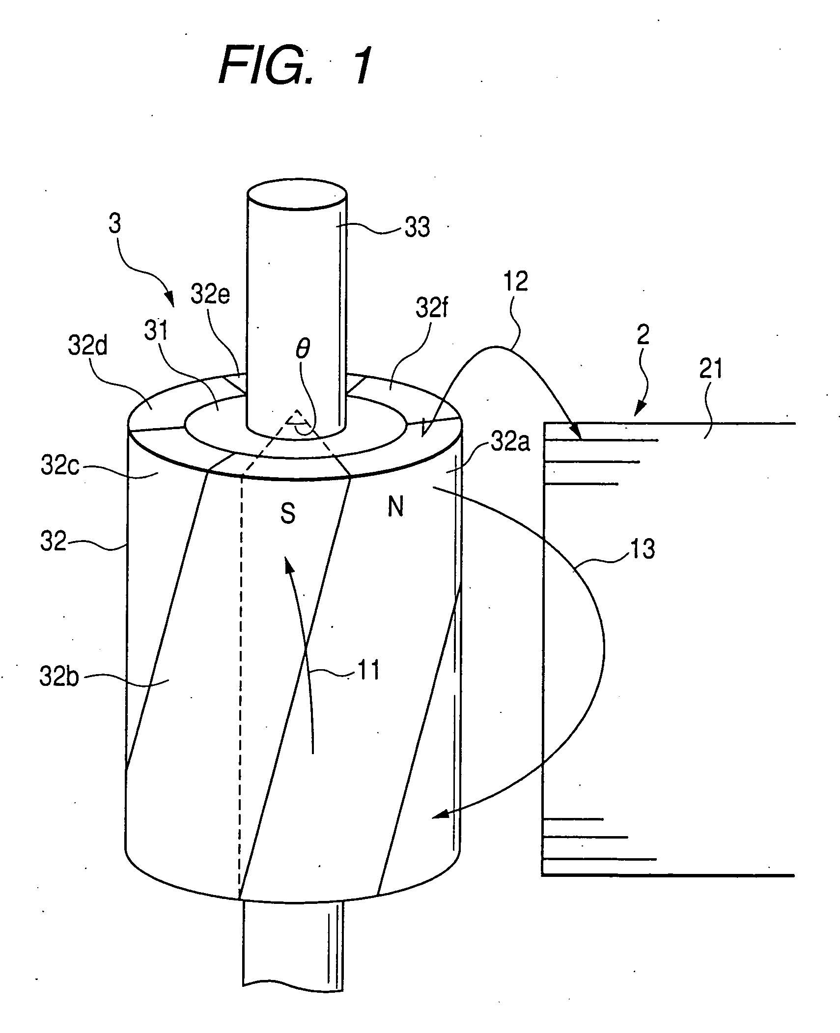
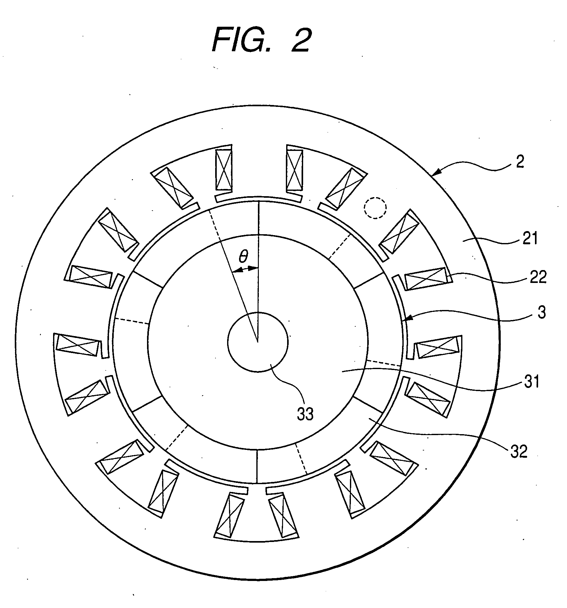
FIGS. 1 and 2 show a permanent magnet rotating machine according to an embodiment 1 of the present invention. Specifically, FIG. 1 is a perspective view showing the essence of the permanent magnet rotating machine and FIG. 2 is a plan view.

As shown in FIGS. 1 and 2, a rotor 3 has a permanent magnet 32 disposed on the outer circumferential face of a rotor iron core 31 secured to a rotor shaft 33. The permanent magnet 32 has the magnetic poles 32a to 32f magnetized so that N poles and S poles are arranged alternately in the circumferential (rotational) direction, with a skew (skew angle θ) provided at the boundary line between magnetic poles 32a and 32b, 32b and 32c, 32c and 32d, 32d and 32e, 32e and 32f, and 32f and 32a. In FIG. 2, the number of magnetic poles of the rotor 3 is 6.

Also, the stator 2 has a plurality of magnetic poles formed by providing a plurality of stator windings 22 on the inner circumference of a stator iron core 21 of almost cylindrical shape and formed with ...


PUM


Abstract

A permanent magnet rotating machine includes a rotor with a permanent magnet having circumferential magnetic poles with a skew at boundaries between magnetic poles of the permanent magnet, and a stator having a stator iron core in an almost cylindrical shape and convex poles protruding inwardly, the rotor being disposed within the stator. A skew angle of the skew is smaller than a theoretical angle θs (electrical angle) and larger than one-half the theoretical angle θs, wherein the theoretical angle θs is defined as,
θs=180×(number of magnetic poles in the rotor)/(smallest integer of which both the number of magnetic poles in the rotor and the number of magnetic poles in the stator are factors) [deg.]

Description

BACKGROUND OF THE INVENTION 1. Field of the Invention This invention relates to a permanent magnet rotating machine such as a servo motor, and more particularly to a permanent magnet rotating machine of small size and high output density in which the cogging torque is reduced. 2. Description of the Related Art In the typical constitution of a permanent magnet rotating machine, a rotor is disposed inside a stator. The stator is formed with a plurality of magnetic poles by providing a plurality of stator windings on the inner circumference of a stator iron core of almost cylindrical shape and formed with a plurality of convex poles protruding inwardly. The rotor has a rotor iron core disposed to be rotatable around a center of the stator as a central axis of rotation. A permanent magnet is provided on the surface or inside of the rotor iron core, and magnetized so that N poles and S poles are arranged alternately in a circumferential (rotational) direction. In this rotating machin...

Claims


Application Information

Patent Timeline
IPC IPC(8): H02K1/22H02K1/27H02K21/14H02K29/03
CPCH02K1/278H02K2201/06H02K29/03
Inventor KOMETANI, HARUYUKIYAMAGUCHI, SHINICHIKIKUCHI, TOMOHIROTAMURA, TAKASHI
Owner MITSUBISHI ELECTRIC CORP
Why Eureka
Try Eureka