Spoke type permanent magnet motor

a permanent magnet motor and rotor technology, applied in the direction of dynamo-electric machines, magnetic circuit rotating parts, magnetic circuit shape/form/construction, etc., can solve the problems of increased manufacturing cost, increased bulk of rotor 1, increased manufacturing cost, etc., and achieve high efficiency

Inactive Publication Date: 2014-01-23
IUCF HYU (IND UNIV COOP FOUNDATION HANYANG UNIV)
View PDF3 Cites 11 Cited by
  • Summary
  • Abstract
  • Description
  • Claims
  • Application Information

AI Technical Summary

Benefits of technology

[0032]The housing is made of the non-magnetic material, and the permanent magnet is ferrite series, th

Problems solved by technology

The size of the magnet 3 or the amount of the magnet is increased in consideration of such a magnetic flux leakage in a prior art, but, in this case, the bulk of the rotor 1 is increased and manuf

Method used


Image

  • Spoke type permanent magnet motor
  • Spoke type permanent magnet motor
  • Spoke type permanent magnet motor

Examples


Embodiment Construction

[0047]Hereinafter, embodiments of the present invention will be described in detail with reference to the accompanying drawings. Therefore, the present invention is not limited to the embodiments. Like reference numerals refer to like elements.

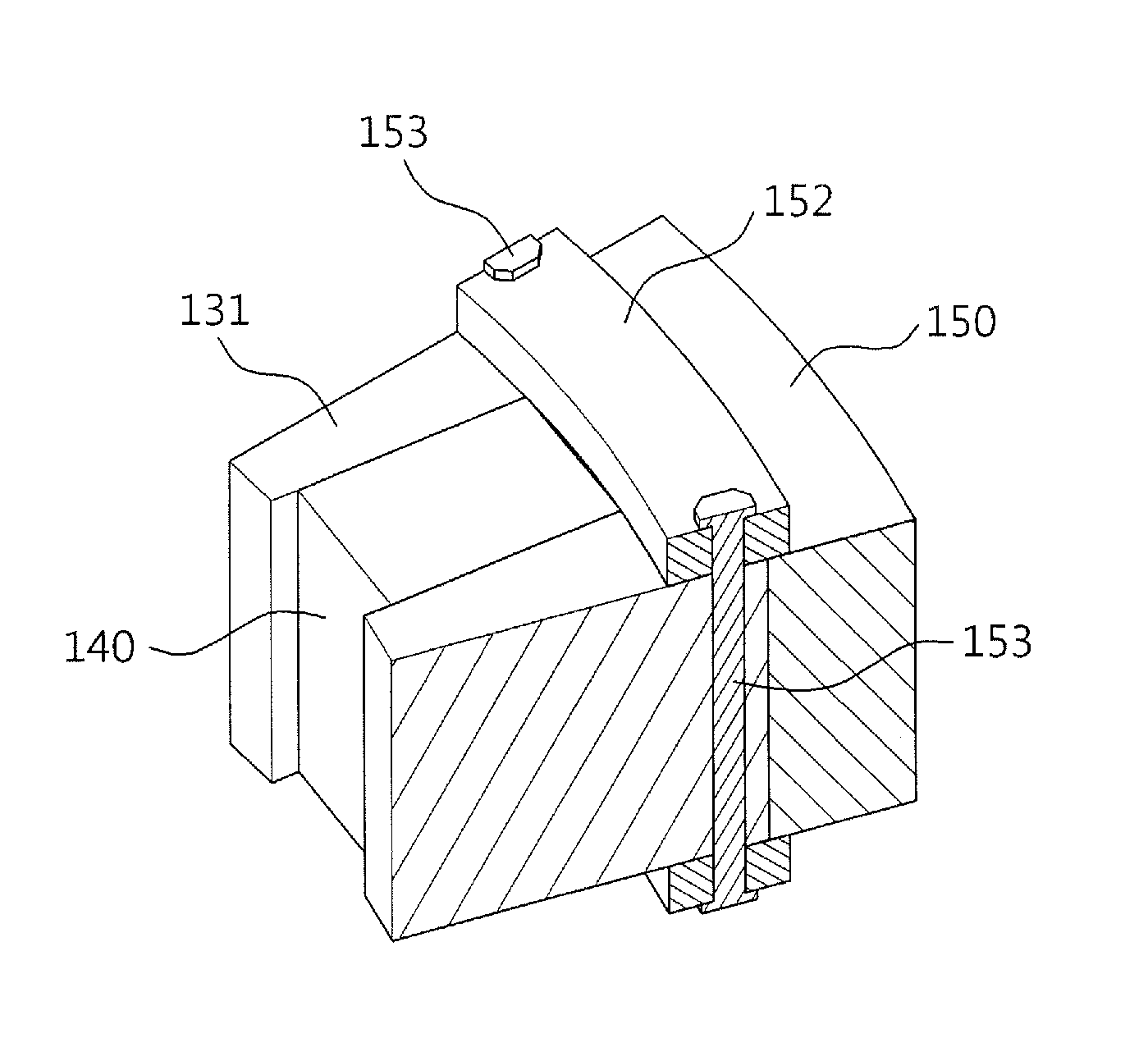
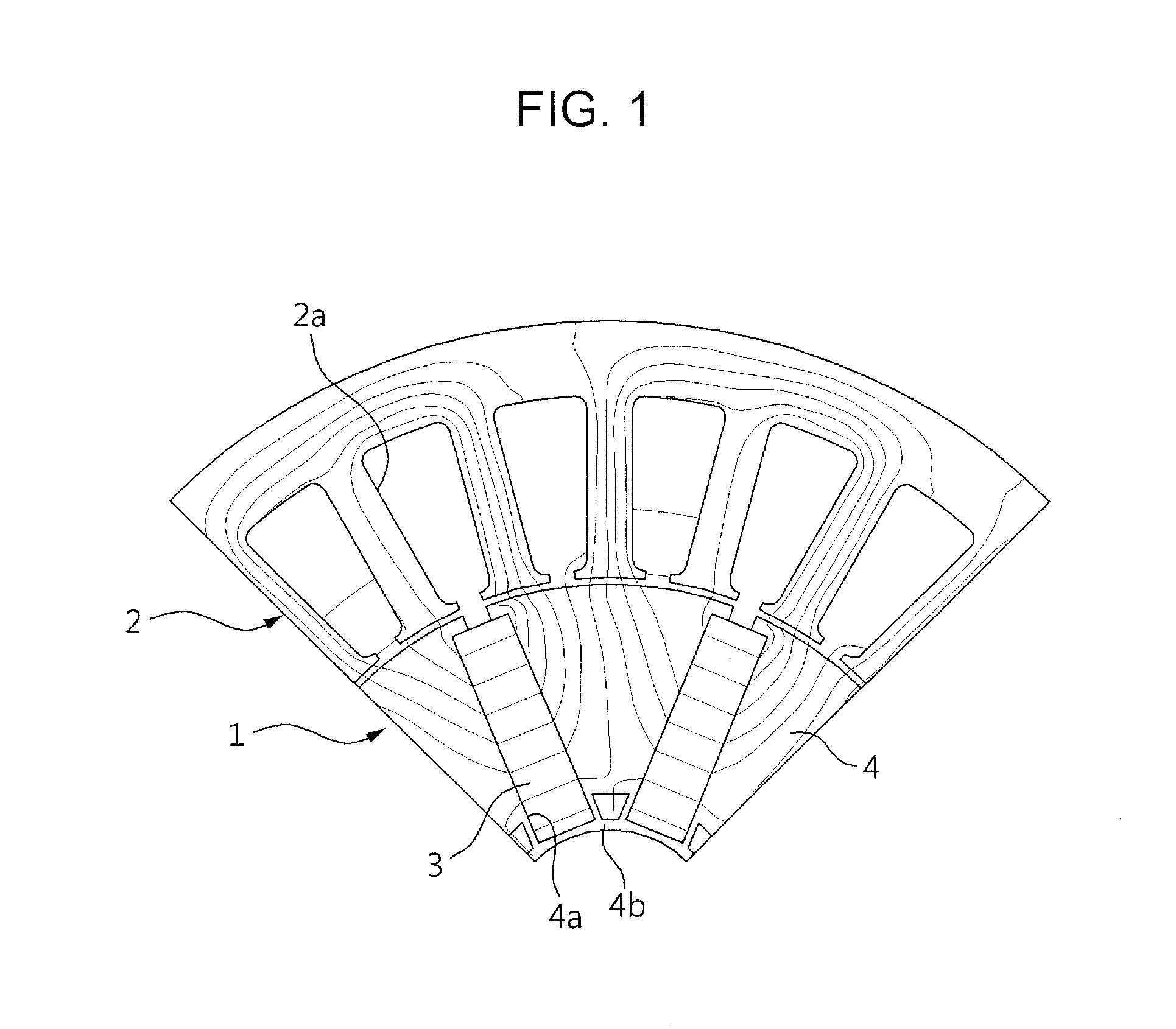
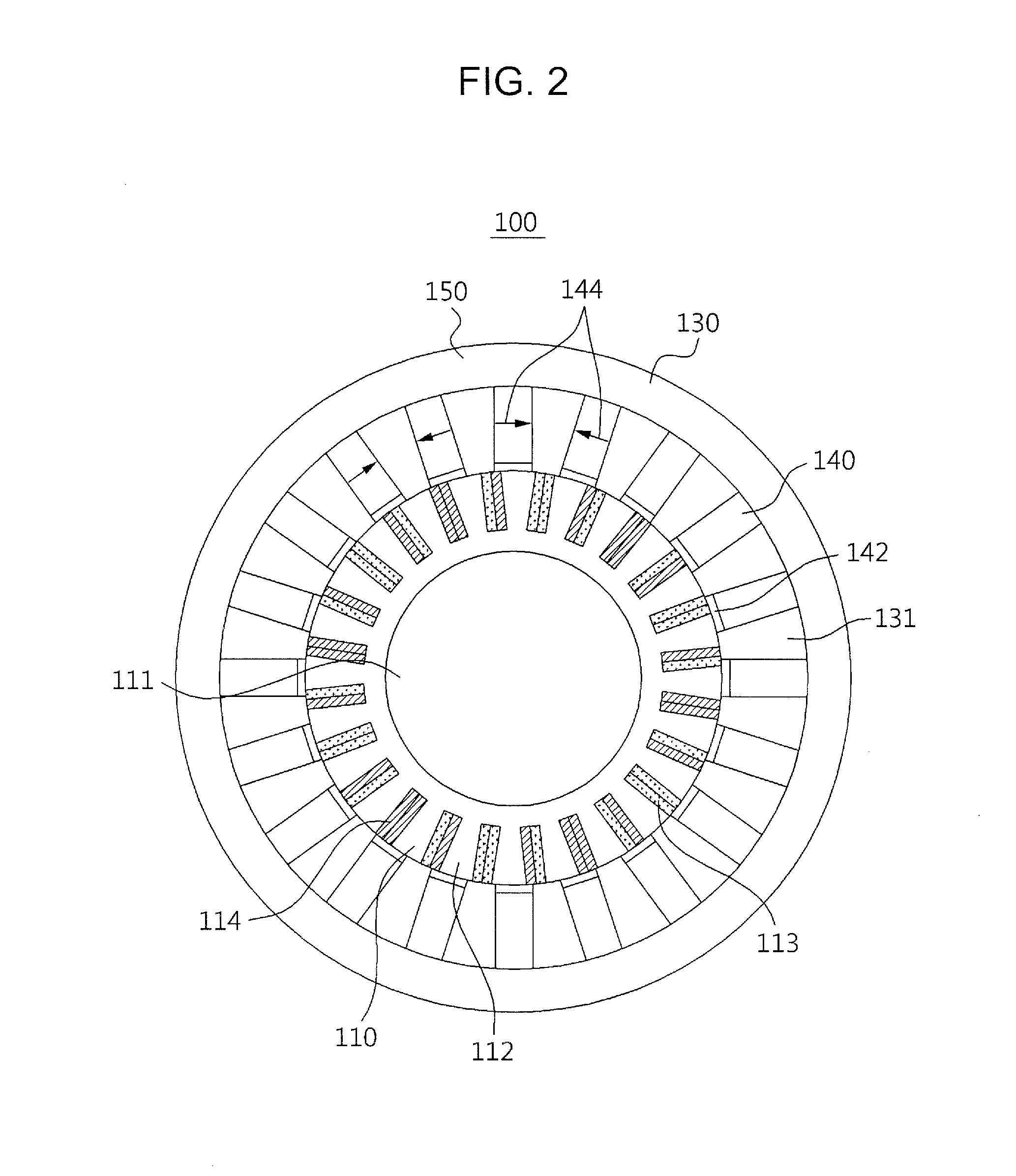
[0048]FIG. 2 is a view for schematically showing a spoke type permanent magnet motor according to one embodiment of the present invention, FIG. 3 is a view for showing an outer rotor of the spoke type permanent magnet motor shown in FIG. 2, FIG. 4 is a view for showing a connecting structure between a rotor housing and rotor core in the outer rotor according to FIG. 3, FIG. 5 is a view for showing variations for the connecting structure between a rotor housing and rotor core in the outer rotor according to FIG. 3, FIGS. 6A and 6B are views for showing a permanent magnet formed with a demagnetization preventing member in the outer rotor according to FIG. 3, FIG. 7 is a graph for representing a d-axis inductance and a q-axis inductance according...


PUM


Abstract

A spoke type permanent magnet motor according to the present invention includes a stator having a stator slot radially disposed according to the center thereof and a stator core radially formed between the stator slots; a spoke type rotor, provided inside or outside the stator, having a rotor core radially disposed in the same direction as the stator slot and stator core and a permanent magnet radially disposed between the rotor core; a first fastening member, made of non-magnetic material, provided at the top and bottom of the rotor, respectively, in the height direction of the rotor; and a second fastening member, made of non-magnetic material, provided to penetrate the rotor core and first fastening member, thereby to maintain high output density and to easily implement miniaturization.

Description

BACKGROUND OF THE INVENTION[0001]1. Field of the Invention[0002]The present invention relates to a spoke type permanent magnet motor, and more particularly, to a permanent magnet motor of an outer rotor type formed in a multipolar spoke type.[0003]2. Description of the Related Art[0004]As enclosed in Korean Examined Patent Publication 10-548716, a spoke type motor, as shown in FIG. 1, includes a rotor 1 having a number of permanent magnets 3, and a stator 2 having a number of slots 2a wound with coils and enclosing the outside of the rotor 1.[0005]The permanent magnet 3 of the rotor 1 is radially disposed on a rotation shaft (not shown). The rotor 1 supports the permanent magnet 3 and includes a cylindrical core 4 forming paths of magnetic flux. The core 4 is formed with a number of steel plates laminated in an axis direction and includes a number of magnet coupling holes 4a for coupling a number of permanent magnets 3. Further, the core 4 includes a supporting section 4b for suppor...

Claims


Application Information

Patent Timeline
IPC IPC(8): H02K1/28H02K1/27
CPCH02K1/28H02K1/27H02K1/2791H02K1/06H02K21/12H02K21/16H02K21/22
Inventor HONG, JUNG-PYOKIM, SUNG-IL
Owner IUCF HYU (IND UNIV COOP FOUNDATION HANYANG UNIV)
Why Eureka
Try Eureka