Absolute position measuring apparatus

a technology of absolute position and measuring apparatus, which is applied in the direction of measuring devices, mechanically converting sensor output, instruments, etc., can solve the problems of increasing manufacturing costs, and achieve the effects of reducing the space of the relay gear, reducing the number of parts, and reducing the size of the apparatus

Active Publication Date: 2009-02-05
MITUTOYO CORP
View PDF5 Cites 14 Cited by
  • Summary
  • Abstract
  • Description
  • Claims
  • Application Information

AI Technical Summary

Benefits of technology

[0021]An object of the present invention is to provide an absolute position measuring apparatus for measuring an absolute position of a spindle, which is easily downsized and simple in manufacture.
[0025]Further, since the relay gear transmits the rotation of the first gear to the second gear, it is not necessary to provide both of a conventional linear key groove and spiral key groove on the spindle. Thus, the spindle can be shortened relative to an axial movable range of the spindle, which easily allows downsizing of the apparatus and reduction in manufacturing costs.
[0028]Further, the first rotor and the second rotor are fixed to the respective ends of the first holder and the second holder to dispose the second rotor on the outer circumference of the first rotor so that the surface of the first stator that faces the first rotor and the surface of the second stator that faces the second rotor are provided in the same plane. Accordingly, the second stator can be provided on the outer circumference of the first stator to form the double structure, or the first stator and the second stator can be integrally provided, thereby lessening a space for the two stators. Furthermore, when the first stator and the second stator are integrally provided, a number of parts can be reduced and assembly procedures can be simplified.
[0030]With this arrangement, since the first gear provided on the second end of the first holder and the second gear provided on the second end of the second holder are provided in parallel in the axial direction of the spindle, a rotation of the first gear can be transmitted to the second gear via the relay gear having the first relay gear, the second relay gear and the shaft that coaxially supports the first relay gear and the second relay gear. Briefly, the relay gear can be a one-stage gear having one rotary shaft. Thus, a space for the relay gear is lessened as compared to a relay gear having a multistage gear system, which allows further downsizing of the apparatus and reduction of the number of the parts, thereby simplifying assembly procedures.

Problems solved by technology

Further, since it is necessary that the key groove 134 is accurately machined on the outer circumference of the spindle 103, manufacturing costs are increased.

Method used


Image

  • Absolute position measuring apparatus
  • Absolute position measuring apparatus
  • Absolute position measuring apparatus

Examples


Embodiment Construction

)

[0038]A micrometer head according to an exemplary embodiment of an absolute position measuring apparatus of the present invention will be described below with reference to the attached drawings.

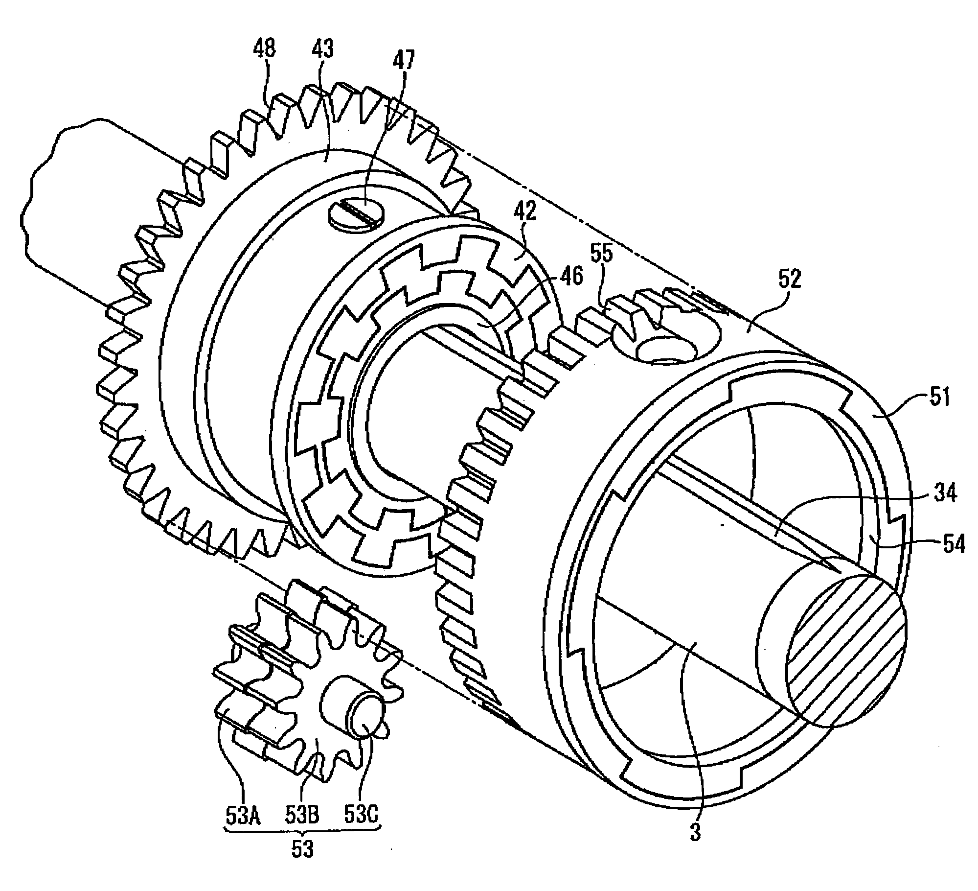
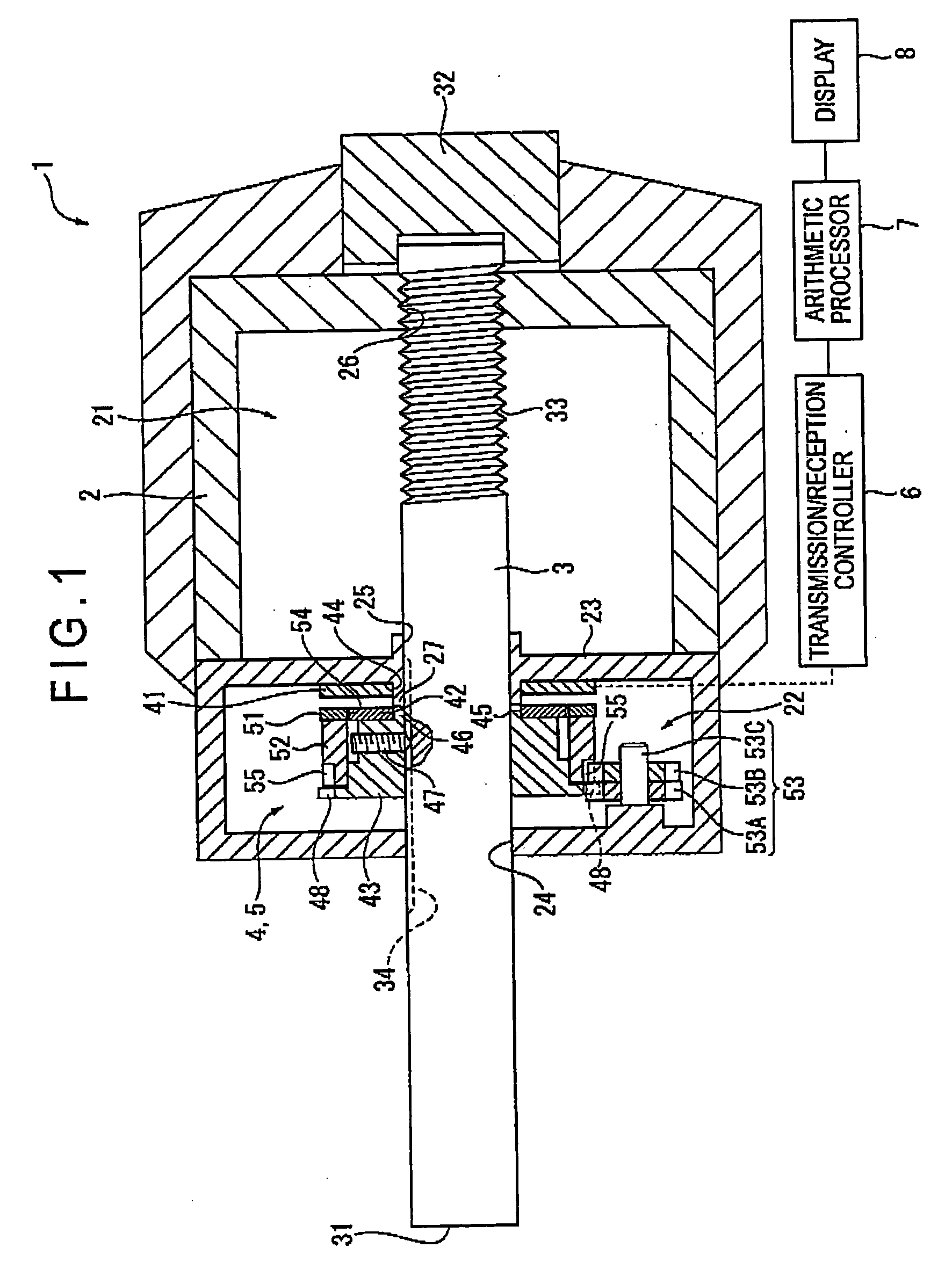
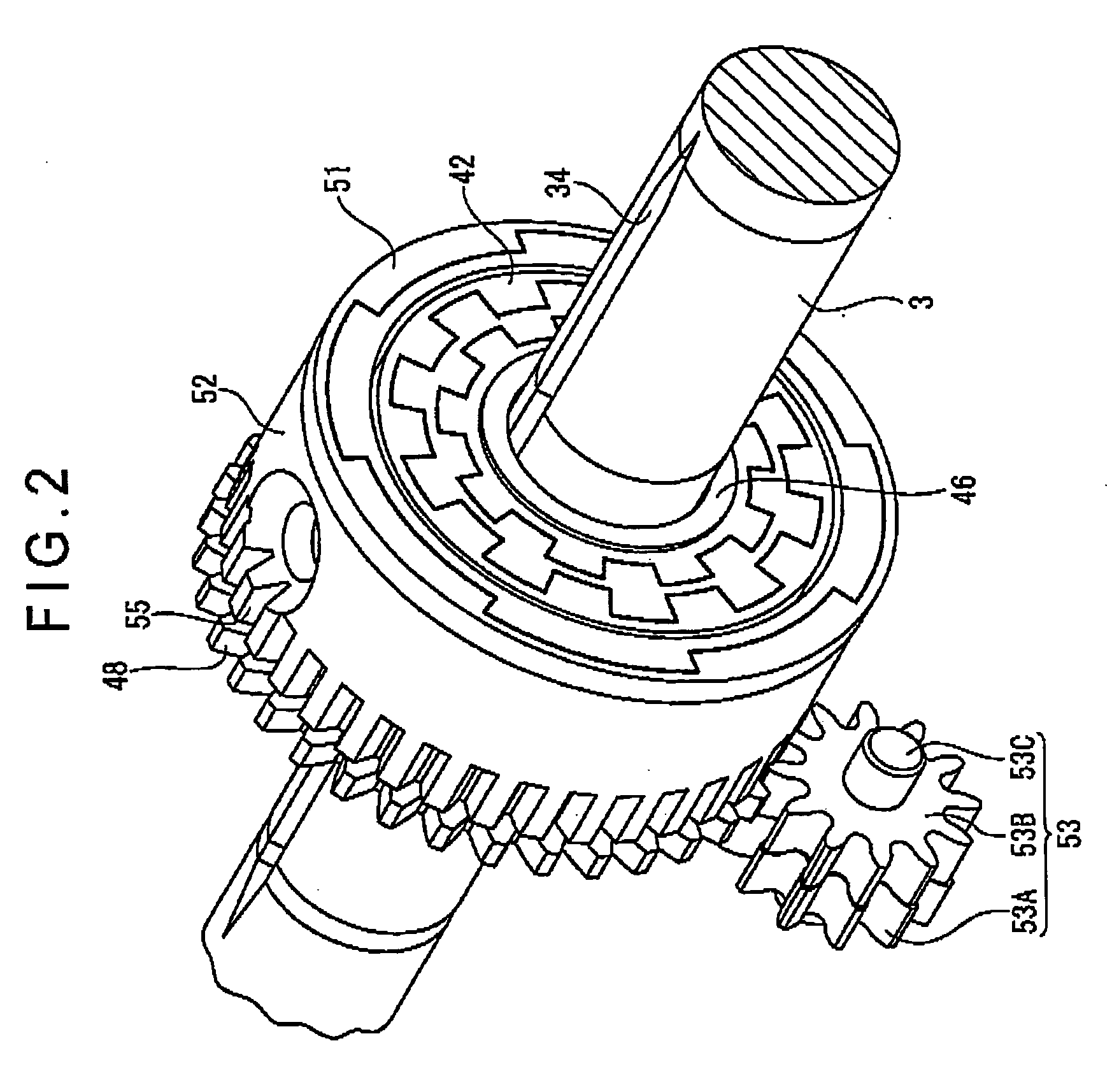
[0039]FIG. 1 is a cross-sectional view showing an arrangement of the micrometer head. FIGS. 2 and 3 are a perspective view and an exploded perspective view respectively showing a main portion of rotary encoders.

[0040]The micrometer head 1 includes: a main body 2; a spindle 3; rotary encoders 4 and 5 as phase signal transmitters; a transmission / reception controller 6; an arithmetic processor 7; a display 8; in which an absolute position of the spindle 3 is calculated by the arithmetic processor 7 to be displayed on the display 8.

[0041]Each component of the micrometer head 1 will be described below with reference to FIGS. 1 to 3.

[0042]The main body 2 is substantially cylindrical and includes accommodating spaces 21 and 22 therein. The accommodating spaces 21 and 22 are separated by a partition...


PUM


Abstract

An absolute position measuring apparatus includes a first rotary encoder that detects a rotation of a spindle as a phase signal which varies in a first cycle and a second rotary encoder that detects the rotation of the spindle as another phase signal which varies in a second cycle. A rotation of a first rotor of the first rotary encoder is transmitted to a second rotor via a relay gear that is meshed with a first gear provided on an outer circumference of a first rotary cylinder and a second gear provided on an outer circumference of a second rotary cylinder. Thus, an absolute position of the spindle is calculated on the basis of two phase signals that are different in cycle. Further, it is not necessary to provide a conventionally-known spiral key groove so that the apparatus can be easily downsized. Manufacturing costs can be also reduced.

Description

BACKGROUND OF THE INVENTION [0001]1. Field of the Invention[0002]The present invention relates to an absolute position measuring apparatus. Specifically, the present invention relates to an absolute position measuring apparatus such as a micrometer head, a micrometer, and a Holtest for measuring an absolute position of a spindle that rotatingly moves in an axial direction.[0003]2. Description of Related Art[0004]Conventionally, in a small-sized measuring apparatus for measuring a length, a size or the like such as a micrometer and a micrometer head, an object is measured by detecting a displacement of a movable member relative to a fixed member (for instance, see Document 1: JP-A-2003-207307 (FIGS. 1 and 4)).[0005]An arrangement of a small-sized measuring apparatus disclosed in Document 1 to detect the displacement of the movable member relative to the fixed member will be described with reference to the attached drawings.[0006]FIG. 6 illustrates a conventional micrometer head 101 a...

Claims


Application Information

Patent Timeline
Patent Type & Authority Applications(United States)
IPC IPC(8): G01B3/18
CPCG01D5/2452G01D5/04G01D2205/26
Inventor SUZUKI, MASAMICHIHAYASHIDA, SHUJITSUJI, SHOZABURO
Owner MITUTOYO CORP
Why Eureka
Try Eureka