Image forming apparatus

Active Publication Date: 2008-09-25
KYOCERA DOCUMENT SOLUTIONS INC
View PDF4 Cites 14 Cited by
  • Summary
  • Abstract
  • Description
  • Claims
  • Application Information

AI Technical Summary

Benefits of technology

[0010]An object of the present invention is to provide an image forming apparatus which can be

Problems solved by technology

However, if the hand or other things touch the outer surface of the photoconductive drum during such an operation, it might cause an image formation defect due to the distortion or damage of the drum surface.
Since other members cannot be arranged in a wide range of this pivotal movement, it is necessary to leave this range as an empty space, which leads to restrictions in the arrangements of the respective mechanisms in the image forming apparatus.
Since an extra space needs to be provided in the appar

Method used


Image

  • Image forming apparatus
  • Image forming apparatus
  • Image forming apparatus

Examples


first embodiment

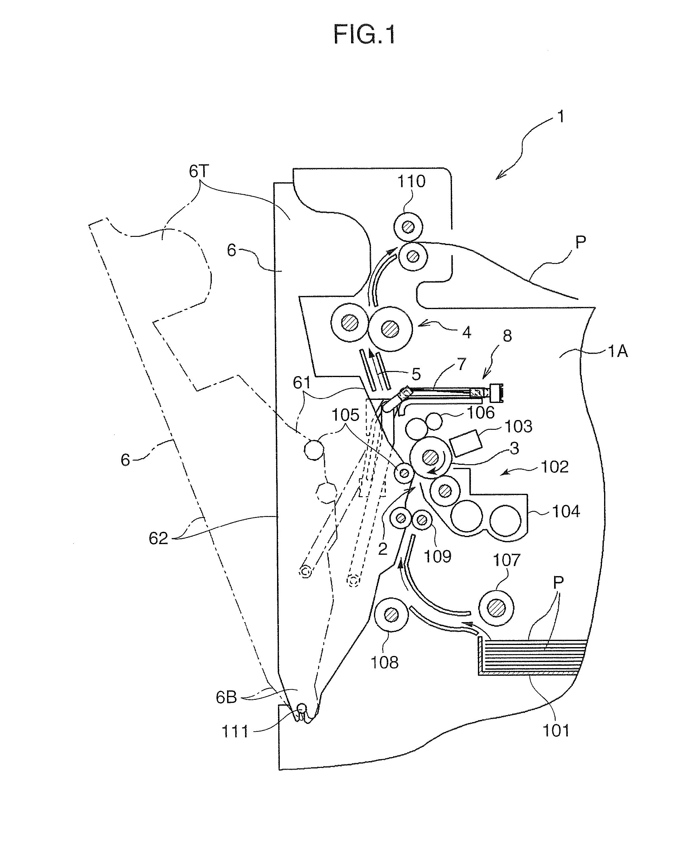
[0028]FIG. 1 is an essential section showing an image forming apparatus 1 according to one embodiment of the present invention. The image forming apparatus 1 is, for example, a copier, a facsimile machine or a printer.

[0029]The image forming apparatus 1 is provided, in an apparatus main body 1A having a housing structure, with a sheet storage unit 101 consisting of a sheet cassette or a sheet feed tray for storing a multitude of transfer sheets (transfer materials), an image forming assembly 102 for forming a toner image and transferring the toner image to a transfer sheet P, a fixing device 4 for fixing the toner image to the transfer sheet P, and a conveyance path 5 for conveying the transfer sheet P from the sheet storage unit 101 to a discharge tray via the image forming assembly 102 and the fixing device 4.

[0030]The image forming assembly 102 includes a photoconductive drum 3 (image bearing member) rotatable in a clockwise direction as shown by an arrow in FIG. 1, and a charger...

second embodiment

[0058]FIGS. 6 and 7 are sections showing an essential portion of an image forming apparatus 10 according to a second embodiment. This image forming apparatus 10 differs from the first embodiment in that two members, i.e. an intermediate conveying device S (opening / closing member) and an opening / closing cover 60 are so supported as to be pivotal with respect to an apparatus main body 1A. Although the image forming apparatus 10 adopts a vertical conveying method similar to the first embodiment, a conveyance path 5 differs in including a main conveyance path 5A (first conveyance path) passing an image forming assembly 102 and a reversing conveyance path (second conveyance path) for conveying a transfer material in a reverse direction at the time of duplex printing. The same parts as those of the image forming apparatus 1 of the first embodiment are identified by the same reference numerals and are either not described or briefly described.

[0059]The main conveyance path 5A is a sheet co...

third embodiment

[0071]In a third embodiment are illustrated a drum cover 70, a front frame 90a and a rear frame 90b different from those of the first embodiment.

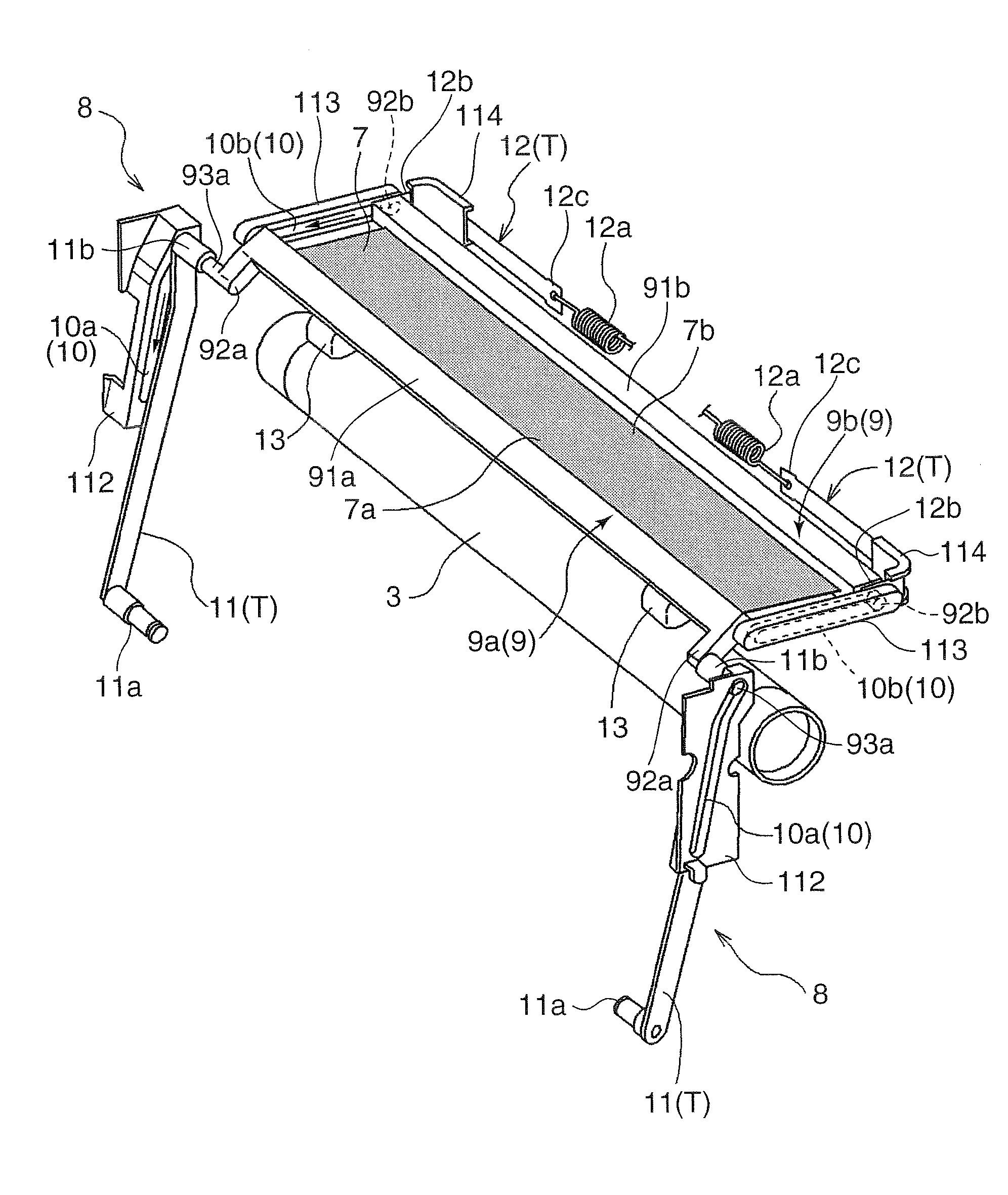
[0072]FIG. 11 is an exploded perspective view showing the drum cover 70, the front frame 90a and the rear frame 90b according to the third embodiment. The third embodiment is similar to the first embodiment in that the front frame 90a is attached to a front edge portion 70a of the drum cover 70 and the rear frame 90b is attached to a rear edge portion 80b in a sliding direction, but is characterized in attachment structures of these frames 90a, 90b.

[0073]The drum cover 70 of this embodiment is a flexible sheet-like drum cover, and a plurality of engaging holes 71, into which locking claws 951 of the front frame 90a and the rear frame 90b to be described later are fittable, are formed along width direction near the front and rear edge portions 70a, 70b thereof. The drum cover 70 is preferably made of polyethylene for the reason of being unl...


PUM


Abstract

An image forming apparatus has an image bearing member and a main body with an internal conveyance path for conveying a transfer material. An opening/closing member is attached to the main body and is displaceable between a closed position and an opened position where the conveyance path is exposed. A cover is set to cover a part of the image bearing member facing the conveyance path when the opening/closing member is open and is retracted from the conveyance path when the opening/closing member is closed. A moving mechanism slides the cover. Front and rear frames are held movably by the moving mechanism and are attached respectively to front and rear edges of the cover in a sliding direction. A tension applying mechanism acts on the frames to apply tension to the cover in the sliding direction during a sliding movement of the cover.

Description

BACKGROUND OF THE INVENTION[0001]1. Field of the Invention[0002]The present invention relates to an image forming apparatus provided with a cover capable of covering an image bearing member.[0003]2. Description of the Related Art[0004]There is known an image forming apparatus in which a vertical conveyance path for vertically conveying a transfer sheet is provided behind an opening / closing cover provided on an apparatus main body having a housing structure and a photoconductive drum is disposed at a back side facing the conveyance path. The opening / closing cover is so provided as to communicate the interior of the apparatus main body with the outside to deal with a jam of a transfer sheet in the conveyance path and other maintenance operations. Thus, if the opening / closing cover is opened, the conveyance path and various parts facing the conveyance path are exposed through an opening. For example, in the case of dealing with a sheet jam, an operator can insert his or her hand into t...

Claims


Application Information

Patent Timeline
IPC IPC(8): G03G21/18
CPCG03G2215/00544G03G2221/1675G03G21/1671G03G21/1633G03G2221/169
Inventor KUSUKAWA, TAKASHIYAMAMOTO, KIYONORI
Owner KYOCERA DOCUMENT SOLUTIONS INC
Why Eureka
Try Eureka