Power transmission unit for vehicle

a transmission unit and transmission unit technology, applied in mechanical equipment, transportation and packaging, gearing, etc., can solve the problems of engine operating efficiency worsening, engine cannot always operate at optimal operating points, and the output shaft cannot be easily changed smoothly, so as to reduce the shock of shifting and uncomfortable feeling resulting from a change in the drive force, the effect of reducing power loss

Inactive Publication Date: 2015-06-18
TOYOTA JIDOSHA KK
View PDF3 Cites 13 Cited by
  • Summary
  • Abstract
  • Description
  • Claims
  • Application Information

AI Technical Summary

Benefits of technology

[0032]When decelerating the vehicle, torque is inputted from the output shaft side. However, the torque inputted from the output shaft to the continuously variable transmission can be cut off to protect the continuously variable transmission by arranging the second clutch device between the driven member of the continuously variable transmission and the output shaft, and by bringing the second clutch device into disengagement.
[0033]If he first clutch device is disengaged under the condition where the speed ratio of the continuously variable transmission is approximated to the speed ratio of the gear train while engaging the second clutch device, the input shaft is connected with the output shaft through the second clutch device and the continuously variable transmission, and the gear train is disconnected from the input shaft. That is, the torque reversing device is disabled to transmit the torque to any of the rotary elements so that the torque transmission between the input shaft and the output shaft through the torque reversing device is interrupted. Consequently, the continuously variable transmission is allowed to alter the speed ratio thereof arbitrarily. To this end, if the friction clutch whose torque capacity can be altered gradually is used as the first and the second clutch devices, the torque of the output shaft may be changed smoothly by gradually changing the torque capacities of the first and the second clutch devices. Consequently, shift shocks and uncomfortable feeling resulting from a change in the drive force can be reduced.
[0034]Thus, the gear train and the torque reversing device are disconnected from both of the input shaft and the output shaft by engaging the second clutch device while disengaging the first clutch device. Therefore, when the torque is transmitted through continuously variable transmission during running, the gear train will not be rotated, and a speed difference among the rotary members will not be widened by the torques delivered from the torque reversing device and the output element. For these reasons, power loss can be reduced, durability of the transmission can be improved, and noises and vibrations can be suppressed.
[0035]As described, according to the present invention, the torque reversing device is comp...

Problems solved by technology

In addition, optimum operating points of the engine are limited.
However, if a geared transmission adapted to shift a gear stage stepwise is used in the vehicle, the engine cannot be always operated at optimum operating points.
That is, if the optimum operating speed exists between the gear stages, the operating efficiency of the engine would be worsened.
In addition, fuel economy will be worsened as a result of establishing high pressure.
However, although both forward and reverse torques are required to propel the vehicle, a torque transmitting direction of the one-way clutch is limited to one direction.
Thus, ...

Method used


Image

  • Power transmission unit for vehicle
  • Power transmission unit for vehicle
  • Power transmission unit for vehicle

Examples


Embodiment Construction

)

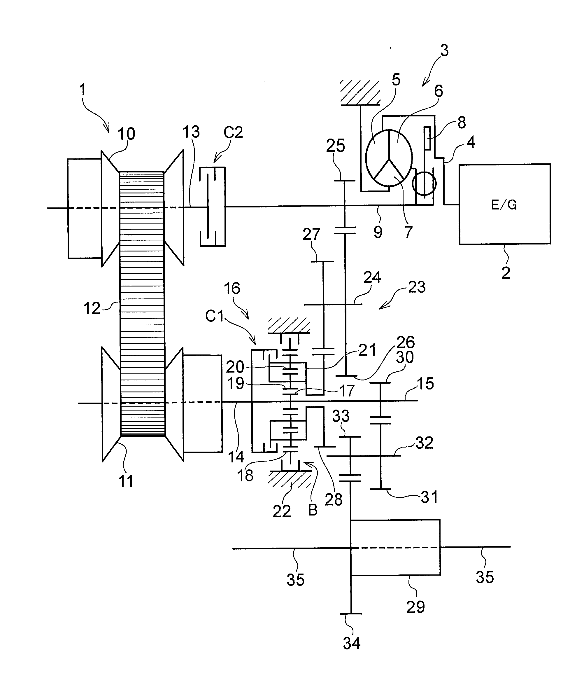
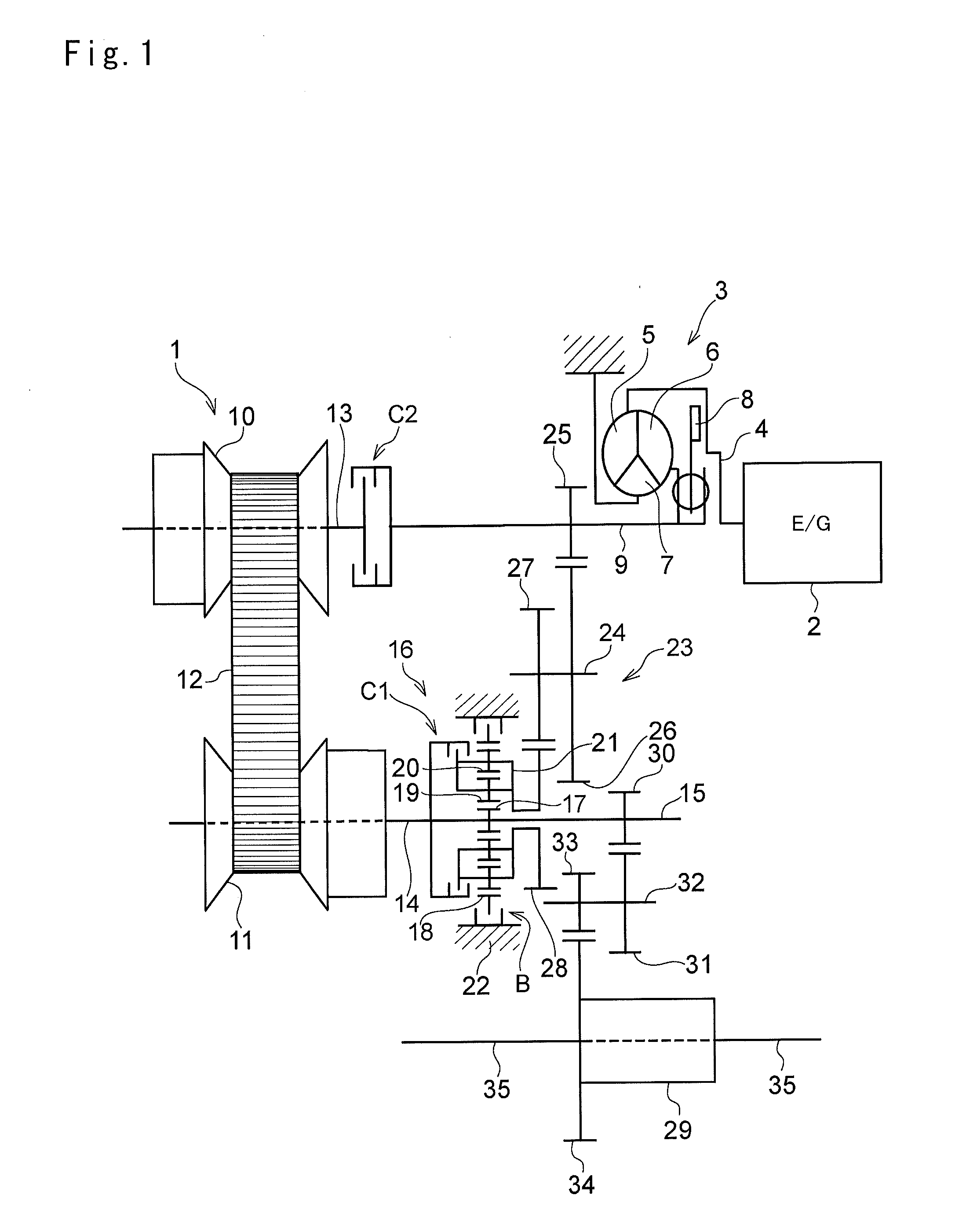
[0052]Next, the present invention will be explained with reference to the accompanying drawings. According to the present invention, there is provided a power transmission unit for transmitting a power of a prime mover such as an engine and a motor, and the power transmission unit has a speed change function. In general, this kind of power transmission unit is called a transmission or a transaxle. More specifically, the present invention is applied to a power transmission unit in which a continuously variable transmission and a gear train of predetermined speed ratio (or a gear ratio) are arranged parallel to each other between an input shaft and an output shaft. In the power transmission unit, a conventional belt-driven continuously variable transmission and a toroidal continuously variable transmission may be used. Specifically, the belt-driven continuously variable transmission is suitable for a power transmission unit of an FF layout vehicle (i.e., a front engine / front wheel dr...


PUM


Abstract

A power transmission unit for a vehicle is provided. In the power transmission unit, torque is transmitted between an input shaft and an output shaft through a continuously variable transmission and a gear train having an intermediate shaft. The continuously variable transmission adapted to alter a speed ratio continuously is disposed between the input shaft to which a torque of a prime mover is inputted and the output shaft that outputs the torque. The gear train is adapted to establish a speed ratio that cannot be established by the continuously variable transmission, and arranged at a different site from positions of the input shaft and the output shaft. The power transmission unit comprises: a torque reversing device that is adapted to perform a differential action among an input element, an output element and a reaction element adapted to rotate the input element and the output element in opposite directions when rotation thereof is halted, and that is disposed coaxially with the output shaft or the intermediate shaft; a first clutch device that connects at least any of two rotary elements of the torque reversing device; and a brake device that halts rotation of the reaction element. The input shaft is connected with the output shaft through the continuously variable transmission, and a second clutch device is disposed on a torque transmitting route from the input shaft to the output shaft via the continuously variable transmission to allow and interrupt torque transmission therethrough. The input shaft is connected with the output shaft through the gear train and the torque reversing device.

Description

TECHNICAL FIELD[0001]The present invention relates generally to a transmission unit for transmitting power of a prime mover of an automobile, and more particularly, to a power transmission unit comprising a transmission route including a continuously variable transmission, and another transmission route arranged parallel to said transmission route.BACKGROUND ART[0002]Generally, an output torque of an internal combustion engine is increased with an increase in a rotational speed, but a vehicle requires a large drive force at low speed and small drive force at high speed. That is, the vehicle required opposite torque characteristic to that generated by the engine. In addition, optimum operating points of the engine are limited. Therefore, the vehicle having the engine as a prime mover is provided with a transmission to alter a speed ratio according to need so that the engine is allowed to be operated at the optimum operating points to generate drive force by altering the speed ratio o...

Claims


Application Information

Patent Timeline
IPC IPC(8): F16H37/02
CPCF16H37/021F16H2037/026F16H2200/2035F16H2200/2005F16H2200/0008F16H37/022
Inventor YOSHIDA, MICHIONAKADA, HIROFUMIKOBAYASHI, DAISUKEYOSHINO, HIROTSUGU
Owner TOYOTA JIDOSHA KK
Why Eureka
Try Eureka