Rotor with inclined magnetic pole and asymmetric salient pole and high-performance permanent magnet motor

A permanent magnet motor, asymmetrical technology, applied in the direction of magnetic circuit rotating parts, magnetic circuits, electromechanical devices, etc., can solve the problems of underutilized components, high torque ripple, difficult to realize, etc., to avoid torque density The effect of excessive attenuation, reduction of harmonic content, and no decrease in torque density

Active Publication Date: 2019-07-16
SHANDONG UNIV
View PDF9 Cites 8 Cited by
  • Summary
  • Abstract
  • Description
  • Claims
  • Application Information

AI Technical Summary

Problems solved by technology

[0005] However, surface embedded permanent magnet motors also have problems: 1) Although the electromagnetic torque of surface embedded permanent magnet motors includes two torque components, permanent magnet torque and reluctance torque, in traditional designs, the two torque components are not Fully utilized, because the permanent magnet torque and reluctance torque reach their respective maximum values ​​with a current phase angle difference of 45 degrees
2) Due to the saliency effect, the surface embedded permanent magnet motor will produce higher torque ripple
However, current literature shows that motor design techniques that reduce torque ripple while maintaining torque density are difficult to achieve

Method used


Image

  • Rotor with inclined magnetic pole and asymmetric salient pole and high-performance permanent magnet motor
  • Rotor with inclined magnetic pole and asymmetric salient pole and high-performance permanent magnet motor
  • Rotor with inclined magnetic pole and asymmetric salient pole and high-performance permanent magnet motor

Examples


Embodiment 1

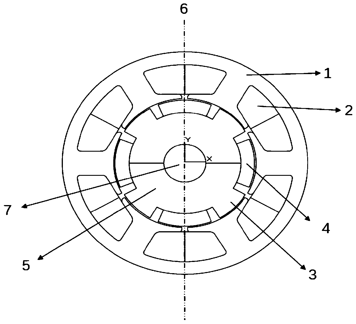
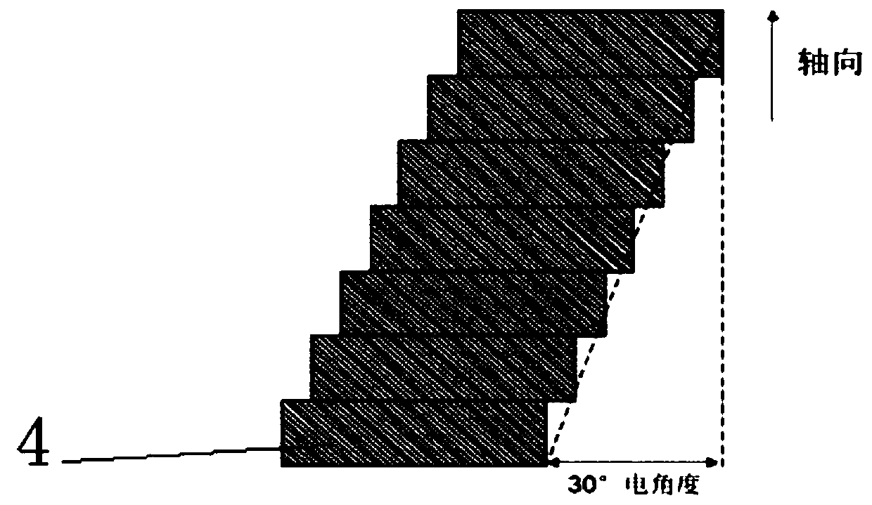
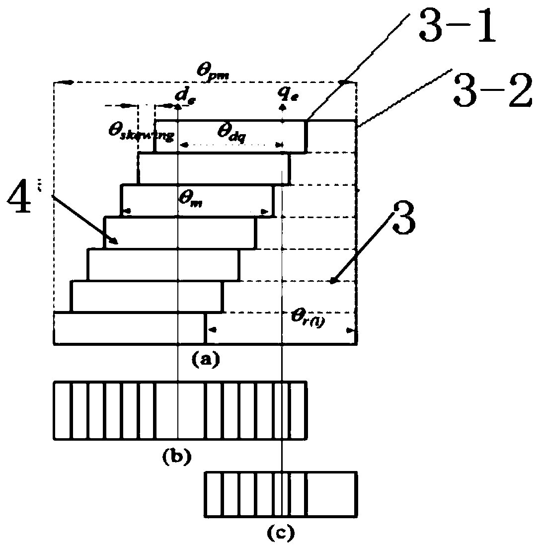
[0033] In the technical solutions disclosed in one or more embodiments, such as Figure 5 with 6 As shown, an asymmetrical rotor with inclined magnetic poles and salient poles includes a rotor core 5-2 and magnetic poles arranged on the rotor iron core 5-2, and each magnetic pole includes salient poles 3 and Rotor slot 5-1, segmented permanent magnets 4 are arranged in the rotor slot 5-1, and the permanent magnets 4 of each segment are extended and arranged along the direction of the rotating shaft 7, and are set in sequence on the circumference of the rotor core 5-2. Misalignment of angles. In this disclosure, the tilted magnetic poles obtained by using the 4-stage dislocation method of permanent magnets can effectively weaken the cogging effect and reduce the cogging torque when applied to permanent magnet motors, and at the same time reduce the harmonic content of back electromotive force to generate sinusoidal or quasi-sinusoidal countermeasures. The electromotive force ...

Embodiment 2

[0049] This embodiment provides a permanent magnet motor with tilted rotor magnetic poles, including a rotor, a stator and a rotating shaft, the rotor and the stator are coaxially arranged, the rotor is arranged inside the stator through the rotating shaft, and there is a gap between the rotor and the stator, so The rotor adopts the rotor with inclined magnetic poles and asymmetry described in Embodiment 1.

[0050] Such as Image 6 As shown, the stator includes a stator core and a stator slot, and a stator winding 2 is arranged in the stator slot, and a radial gap 18 is formed between the stator winding 2 and the outer periphery of the rotor 5 .

[0051] The stator slots are arranged at equal intervals along the circumferential direction on the inner periphery of the stator 1 , and extend from the side of the stator core to the direction of the rotating shaft in a convex shape. The stator can be a common six-slot structure.

[0052] In Embodiment 2, by using an asymmetrical...


PUM


Abstract

The invention provides a rotor with an inclined magnetic pole and an asymmetric salient pole and a high-performance permanent magnet motor; the magnetic pole inclined pole is implemented in one magnetic pole polar distance, and the salient pole is arranged on one side of the magnetic pole and has asymmetry in the circumferential direction. According to the rotor design of the high-performance permanent magnet motor, the torque pulsation can be reduced, and the reduction of the output torque after torque pulsation can be effectively avoided, the low-torque pulsation of the motor is realized, the high-torque density operation is achieved, and the performance of the motor is greatly improved; the method specifically comprises the following steps that 1) the torque of a tooth groove is reduced; 2) the sinusoidal or quasi-sinusoidal back electromotive force is generated to reduce the torque pulsation; and 3) the axial direction of the adjacent magnetic poles is not overlapped, so that the overlarge attenuation of the torque density is avoided; and by virtue of the asymmetric salient pole rotor structure, the maximum values of the magnetic resistance torque and the permanent magnet torque are overlapped under the same or similar current phase angles, so that the torque loss caused by the magnetic pole inclined pole is made up by increasing the utilization rate of the two torque components, the low torque pulsation of the motor is ensured, and meanwhile, the high torque density is kept.

Description

technical field [0001] The present disclosure relates to the relevant technical field of permanent magnet motors, in particular to a rotor with inclined magnetic poles and asymmetric salient poles and a high-performance permanent magnet motor. Background technique [0002] The statements in this section merely provide background information related to the present disclosure and may not necessarily constitute prior art. [0003] With the development of rare earth permanent magnet materials, permanent magnet motors are widely used in various fields such as electric vehicles, wind power generation, and ship propulsion due to their significant advantages such as high efficiency, high power density, and high reliability. Due to the various structures of permanent magnet motors, the optimal design of the structure of permanent magnet motors can maximize the performance of permanent magnet motors in all aspects. [0004] According to the placement position of the permanent magnet ...

Claims


Application Information

Patent Timeline
Patent Type & Authority Applications(China)
IPC IPC(8): H02K1/24H02K1/27
CPCH02K1/24H02K1/2706H02K2201/06H02K29/03H02K2213/03Y02T10/64
Inventor 赵文良李玉靖刘炎
Owner SHANDONG UNIV
Why Eureka
Try Eureka