Large effective area low attenuation optical fiber

Inactive Publication Date: 2012-07-10
CORNING INC
View PDF6 Cites 240 Cited by
  • Summary
  • Abstract
  • Description
  • Claims
  • Application Information

AI Technical Summary

Benefits of technology

[0008]One aspect of the invention is an optical fiber that includes a glass core extending from a centerline to a radius R1, wherein R1 is greater than about 5 μm, and a glass cladding surrounding and in contact with the core. The cladding includes a first annular region extending from the radius R1 to a radius R2, the first annular region having a radial width W1=R2−R1. The cladding also includes a second annular region extending from the radius R2 to a radius R3, the second annular region having a radial width W2=R3−R2. In addition, the cladding includes a third annular region extending fr

Problems solved by technology

Generally, an optical waveguide fiber having a large effective area (Aeff) reduces non-linear optical effects, including self-phase modulation, four-wave-mixing, cross-phase modulation, and non-linear scattering processes, all of which can cause degradation of signals in high powered systems.
On the other hand, an increase in effective area o

Method used


Image

  • Large effective area low attenuation optical fiber
  • Large effective area low attenuation optical fiber
  • Large effective area low attenuation optical fiber

Examples


examples

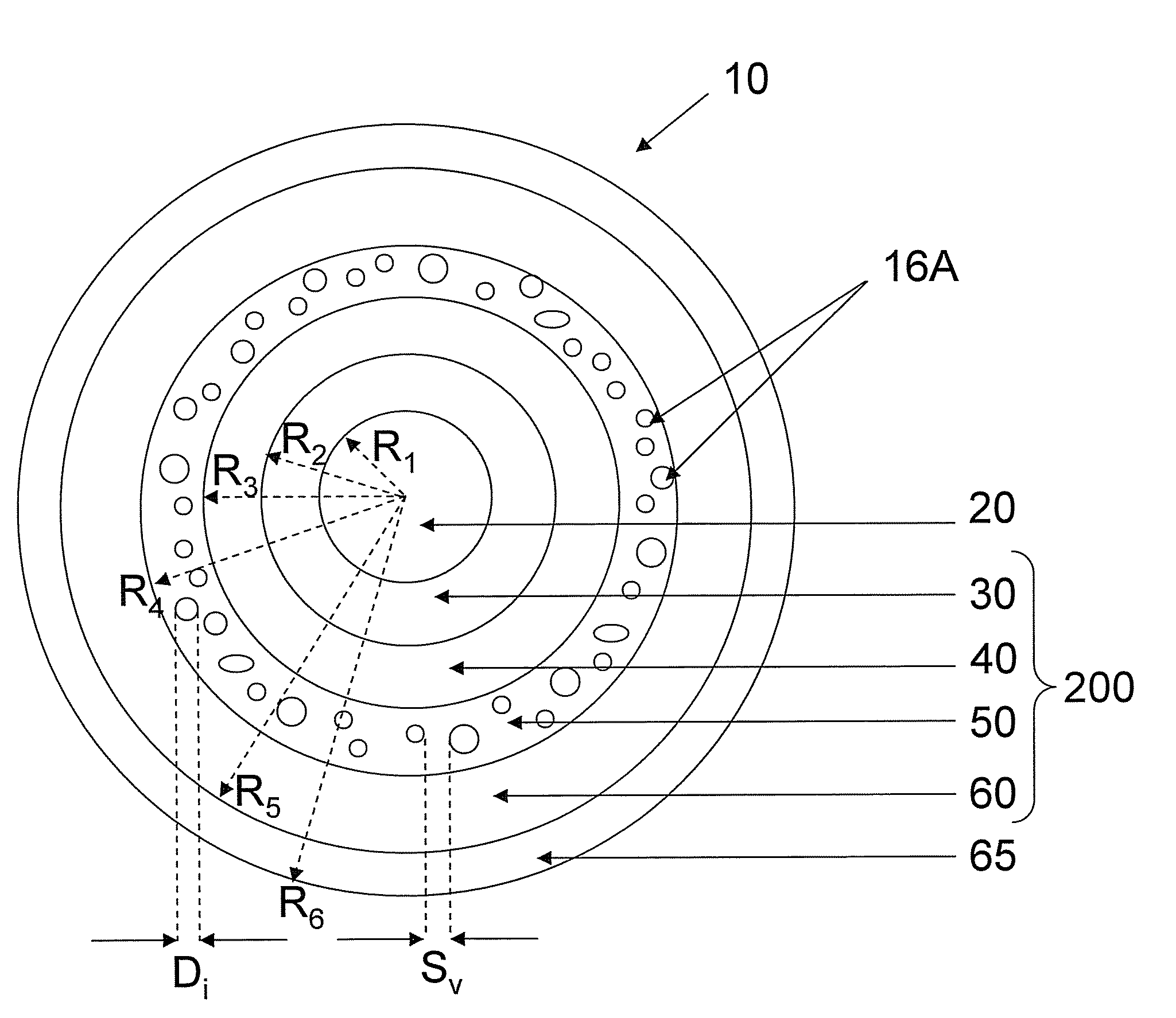
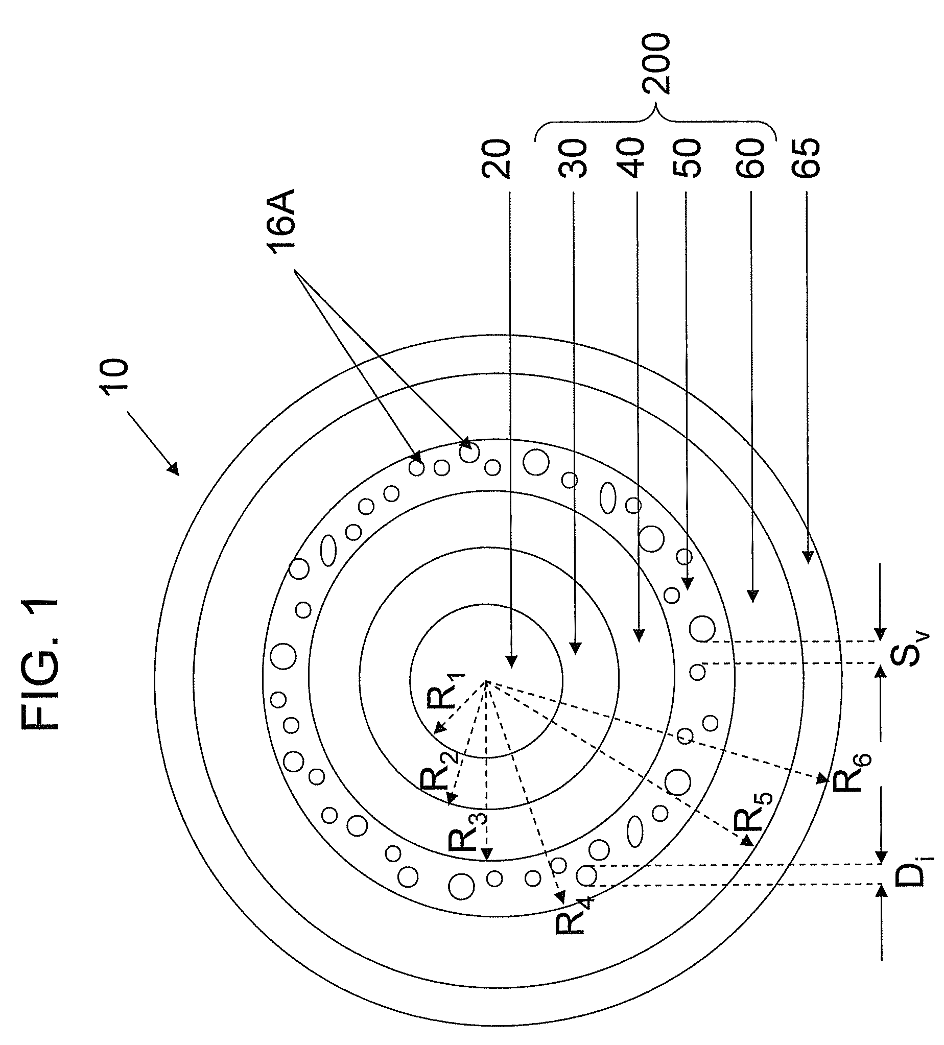
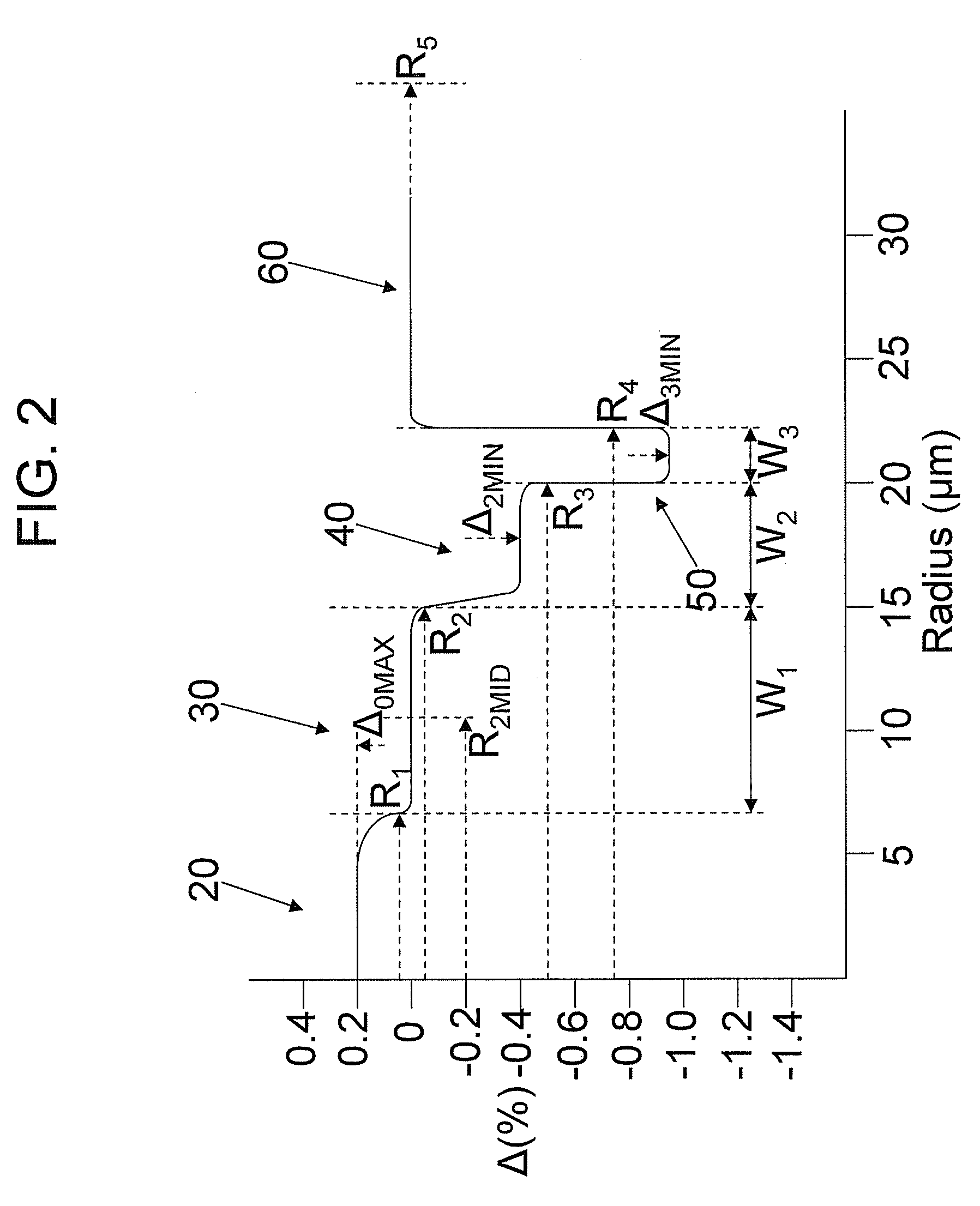
[0048]Examples 1-5 set forth refractive index profile parameters and optical properties of modeled optical fibers in accordance with embodiments disclosed herein and illustrated, for example, in FIGS. 1-2. Table 1 lists refractive index profile parameters of Examples 1-5 and Table 2 lists modeled optical properties of Examples 1-5.

[0049]

TABLE 1Refractive Index Profile ParametersExample12345Δ0MAX (%)0.20.1980.1980.1960.16R1 (μm)7.177.177.37.38.15Δ1MID (%)00000R2 (μm)14.512.411.4511.112.1W1 (μm)7.335.234.153.83.95Δ2MIN (%)−0.4−0.3−0.25−0.18−0.18R3 (μm)19.519.519.52122W2 (μm)57.18.059.99.9Δ3MIN (%)−1−1−1−1−1.3R4 (μm)2222222324W3 (μm)2.52.52.522core alpha88888|V2| (%-μm2)6867.962.357.260.8

[0050]

TABLE 2Modeled Optical PropertiesExample12345MFD at 1550 nm13.9413.7413.6713.7215.11(μm)Aeff at 1550 nm153.0150.1150.0150.9184.2(μm2)Dispersion at 155020.9221.3921.6821.5621.83nm (ps / nm / km)Dispersion Slope0.06430.06470.06470.06430.0646at 1550 nm(ps / nm2 / km)Kappa at 1550 nm325.3330.4335.3335.4337.9...


PUM


Abstract

Optical waveguide fiber that has large effective area and low loss characteristics, such as low attenuation and low bend loss. The optical waveguide fiber includes a dual trench design wherein an annular region closer to the core is preferably doped with at least one downdopant such as fluorine, which annular region is surrounded by another annular region that preferably includes closed, randomly dispersed voids.

Description

CROSS-REFERENCE TO RELATED APPLICATIONS[0001]This application claims the benefit of, and priority to U.S. Provisional Patent Application No. 61 / 155,741 filed on Feb. 26, 2009 entitled, “Large Effective Area Low Attenuation Optical Fiber”, the content of which is relied upon and incorporated herein by reference in its entirety.BACKGROUND OF THE INVENTION[0002]1. Field of the Invention[0003]The present invention relates generally to optical fiber, and particularly to optical fibers that have large effective area and low bend loss at 1550 nm.[0004]2. Technical Background[0005]Optical amplifier technology and wavelength division multiplexing techniques are typically required in telecommunication systems that provide high power transmissions for long distances. The definition of high power and long distances is meaningful only in the context of a particular telecommunication system wherein a bit rate, a bit error rate, a multiplexing scheme, and perhaps optical amplifiers are specified. ...

Claims


Application Information

Patent Timeline
IPC IPC(8): G02B6/02
CPCG02B6/02019G02B6/02357G02B6/02366G02B6/0365G02B6/03661G02B6/02266
Inventor BICKHAM, SCOTT ROBERTSONLI, MING-JUN
Owner CORNING INC
Why Eureka
Try Eureka