LED lighting device

a technology of led lighting and diodes, which is applied in the direction of cathode-ray/electron beam tube circuit elements, fixed installations, lighting and heating apparatus, etc., can solve the problems of decreased operating lifespan, increased power loss of led elements, and deterioration of optical output and optical efficiency, so as to achieve rapid discharge of heat generated

Inactive Publication Date: 2011-06-30
SOLARKOR
View PDF9 Cites 242 Cited by
  • Summary
  • Abstract
  • Description
  • Claims
  • Application Information

AI Technical Summary

Benefits of technology

[0018]An embodiment of the present invention can provide a lamp type LED lighting device that can rapidly discharges heat generated from an LED element that influences an optical output and a lifespan of the LED lighting device through a lamp type frame having a convection heat dissipation structure in which ventilation is smooth, and prevent an LED light source from glaring and widely diffuse a light source without optical attenuation by using a side reflection member and a diffusion lens and a diffusion cover.
[0019]Another embodiment of the present invention can provide line ty...

Problems solved by technology

However, when a driving current of the LED element increases in order to acquire a high-luminance, high-power lighting source, the power loss of the LED element increases, as a result, most of electric energy is converted into heat and a junction portion of the LED element is in a high-temperature state.
Even though a current flowing through the LED element is uniform, when the temperature of the junction portion increases, the LED element has characteristics in that an optical output and optical efficiency thereof deteriorate and the operating lifespan thereof decreases.
However, such a scheme has a problem in that a projection angle of the LED light source, optical attenuation increases by the ivory white diffusion cover to decrease illumination and thermal accumulation occurs in the diffusion cover to easily deteriorate the LED element, to there...

Method used


Image

  • LED lighting device
  • LED lighting device
  • LED lighting device

Examples


Embodiment Construction

]

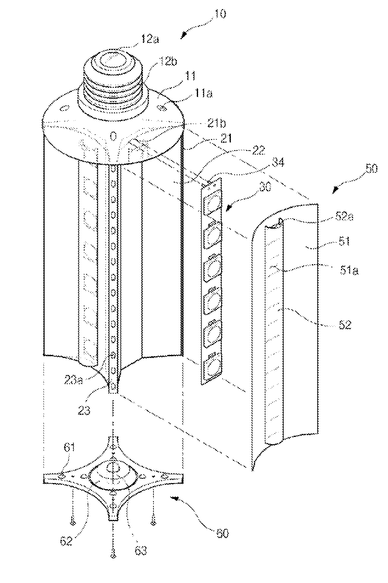
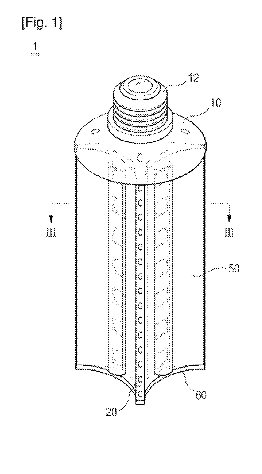
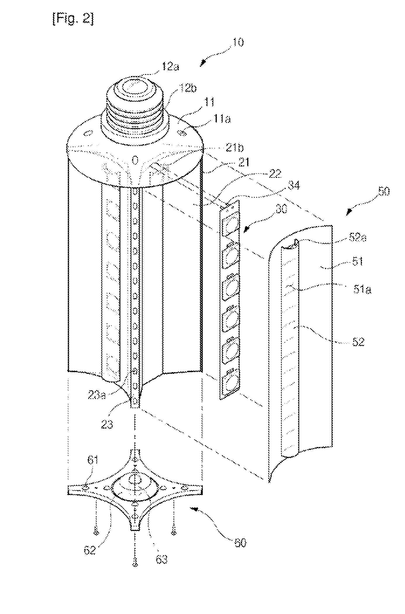
[0074]A lamp type LED lighting device according to an embodiment of the present invention includes a housing cover 10, a heat dissipating frame 20, an LED module 30, a power supply module unit 40, a side reflecting member 50, a frame cover 60, a light sensor 70, and a control unit 80 as shown in FIGS. 1 to 14.

[0075]The housing cover 10 preferably has a disk shape and includes a housing 11, having at least one housing hole 11a and a socket 12 fixed to the top of the housing 11 and connected with an external power supply as shown in FIGS. 1 and 2.

[0076]The housing hole 11a serves as a movement passage of air that allows heat generated from the LED module 30 to be described later to be discharged and cooled by air. The socket 12 includes a positive electrode connection terminal 12a and a negative electrode connection terminal 12b to supply a power to the power supply module unit 40 to be described later as shown in FIG. 2.

[0077]The heat dissipating frame 20 includes a frame body 21 th...


PUM


Abstract

The present invention relates to a lighting device using an LED. One embodiment of the invention provides a lamp-shaped LED lighting device that can replace a known lighting device. The lamp-shaped LED lighting device promptly emits the heat generated by an LED element, which influences the optical output and the lifespan of the LED lighting device, through a lamp-shaped frame with a heat-ventilation structure that facilitates air circulation. In addition, the lamp-shaped LED lighting device prevents glare from an LED light source by using a lateral reflecting member, a diffusion lens and a diffusion cover and diffuses the light from the light source widely without optical attenuation. Another embodiment of the invention provides a tube and panel-shaped LED lighting devices that can be replaced with a previous tube-shaped fluorescent light and a panel-shaped lighting device. The tube and panel-shaped LED lighting devices rapidly emit the heat generated by an LED element, which influences the optical output and the life span of the LED lighting device, through a tube and panel-shaped frame with a heat-sink structure. In addition, the tube and panel-shaped LED lighting devices prevent glare from the LED light source by optically arranging a curved reflecting plate, a diffusion plate and a diffusion window which include a diffusion lens at the upper portion of the LED element. Furthermore the tube and panel-shaped LED lighting devices diffuse the light from the LED light source widely without optical attenuation.

Description

TECHNICAL FIELD[0001]The present invention relates to a lighting device, and more particularly, to a lighting-emitting diode (LED) lighting device that prevents a light output and a lifespan of an LED element from being deteriorated and emits uniform lighting without glaring and optical attenuation with a convection dissipation type frame rapidly dissipating heat by using the LED element as a light source.BACKGROUND ART[0002]In recent years, the LED element has been in the spotlight as a light source of diversified lighting devices. The LED element has advantages such as a lower heat dissipating amount, lower power consumption, a longer lifespan, higher impact-resistance, and the like than a known lighting source. Further, during manufacturing, since mercury or discharging gas is not used like a 00fluorescent lamp, the LED element has an advantage of not causing environmental pollution.[0003]In the case in which appropriate power is supplied and an appropriate heat dissipating unit ...

Claims


Application Information

Patent Timeline
IPC IPC(8): H01K1/62F21V29/00
CPCF21K9/00F21V29/83F21S4/008F21S8/033F21S8/04F21V5/008F21V7/005F21V13/04F21V23/00F21V23/0442F21V29/004F21Y2101/02F21Y2103/003F21Y2111/005F21K9/135F21V29/507F21S2/005F21S4/28F21K9/232F21Y2103/10F21Y2115/10F21Y2107/30F21V5/04F21V5/045F21Y2105/16
Inventor KIM, HYUN MIN
Owner SOLARKOR
Why Eureka
Try Eureka