Anti-dazzle LED illumination device

A LED lighting and anti-glare technology, which is applied to lighting devices, components of lighting devices, lighting and heating equipment, etc., can solve problems such as easy glare, and achieve large-scale application, good anti-glare effect, and scientific design Effect

Inactive Publication Date: 2008-07-16
史杰
View PDF0 Cites 31 Cited by
  • Summary
  • Abstract
  • Description
  • Claims
  • Application Information

AI Technical Summary

Problems solved by technology

The LED light source has the characteristics of small size and high brightness, so it is easy to generate glare in the application of LED lighting, and the above-mentioned light distribution design methods have not specially set up a structure to prevent glare

Method used


Image

  • Anti-dazzle LED illumination device
  • Anti-dazzle LED illumination device
  • Anti-dazzle LED illumination device

Examples


Embodiment 1

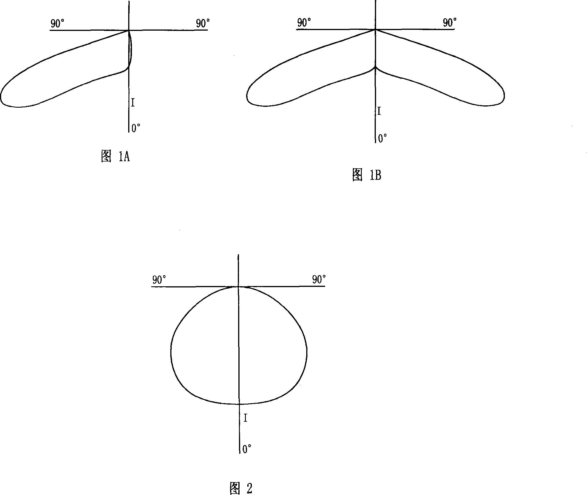
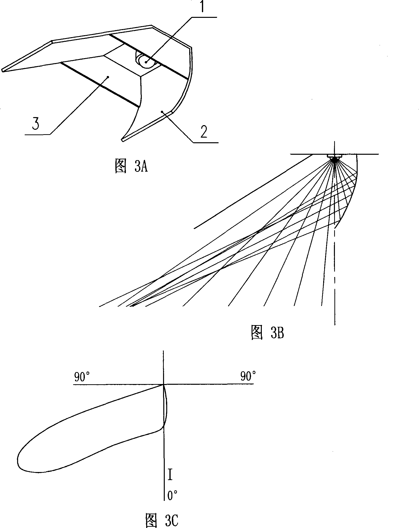
[0079]As shown in Figure 5, an asymmetric light distribution LED anti-glare lighting module AM ​​consists of multiple LED lighting units U with asymmetric light distribution and anti-glare characteristics that are repeatedly arranged along the axis direction of the composite reflector 2 get. The LED lighting unit U constituting the LED anti-glare lighting module AM, its light distribution characteristic perpendicular to the axis direction of the composite reflector 2 is provided by the composite reflective surface of the composite reflector 2, which is a wing-type light distribution; The glare in the axial direction of the type reflector 2 is suppressed by the shielding grid bar 3 . The light distribution of the LED anti-glare lighting module AM ​​with asymmetrical light distribution is similar to the light distribution of a single LED lighting unit Ud, which is a flank light distribution.

[0080] In the shown asymmetrical light distribution LED anti-glare lighting module AM...

Embodiment 2

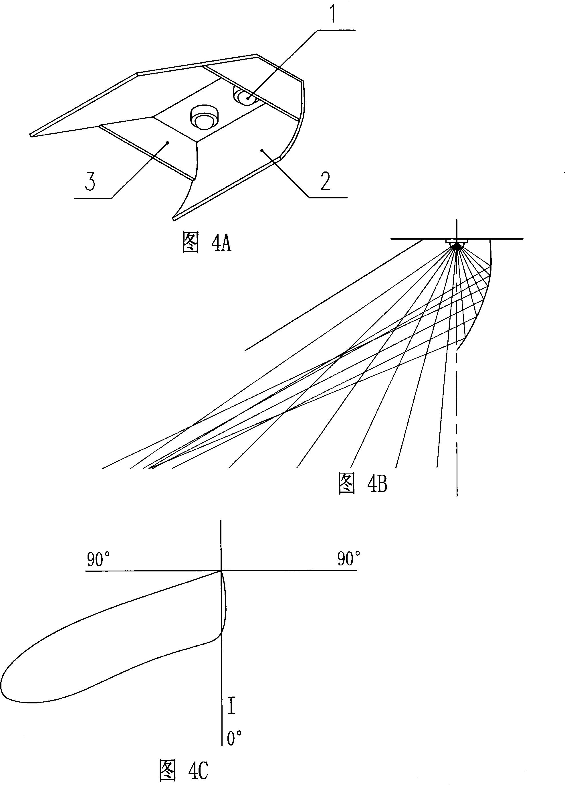
[0083] As shown in Figure 6, another LED anti-glare lighting module AM ​​with asymmetric light distribution consists of a plurality of LED lighting units U with asymmetric light distribution and anti-glare characteristics repeated along the axis direction of the compound reflector 2. Arranged to get. The LED lighting unit U constituting the LED anti-glare lighting module AM, its light distribution characteristic perpendicular to the axis direction of the composite reflector 2 is provided by the composite reflective surface of the composite reflector 2, which is a wing-type light distribution; The glare in the axial direction of the type reflector 2 is suppressed by the shielding grid bar 3 . The light distribution of the LED anti-glare lighting module AM ​​with asymmetrical light distribution is similar to the light distribution of a single LED lighting unit U, which is a wing-type light distribution.

[0084] In the shown asymmetric light distribution LED anti-glare lighting...

Embodiment 3

[0088] As shown in Figure 7, a LED anti-glare lighting module SM with symmetrical light distribution, the LED lighting unit U with asymmetrical light distribution and anti-glare characteristics that make up the LED anti-glare lighting module SM, and the composition of the above-mentioned Figure 6 and The LED lighting units U of the LED anti-glare lighting module AM ​​with asymmetrical light distribution shown in Embodiment 2 are exactly the same, except that the arrangement of the LED lighting units U along the axial direction of the composite reflector 2 changes from repeated arrangement to continuous Repeat in reverse order. The obtained symmetrical light distribution LED anti-glare lighting module SM, its light distribution is similar to the light distribution mirror superposition of the asymmetric light distribution LED anti-glare module AM ​​shown in Figure 6 and Embodiment 2, that is, the mirror superposition of the flank light distribution , for batwing light distributi...


PUM


Abstract

An anti-glare LED illuminating apparatus belongs to the semiconductor illuminating technology field and is characterized by being provided with an anti-glare LED illuminating unit U, which comprises an LED light source 1, a combined type reflector 2 and a shielding lace bar 3, or an LED anti-glare illuminating module or an LED anti-glare illuminating die set consisting of the anti-glare LED illuminating unit, the LED light source is arranged between two adjacent shielding lace bars 3, the inner wall of the combined type reflector 2 is an asymmetry reflection plane, optical intensity is distributed asymmetrically along the direction vertical to the combined type reflector 2 axes, a light distribution curve is of lateral wing type, the shielding lace bar 3 limits the glare generated by the LED light source 1 along the axial direction of the combined type reflector 2. The invention has scientific design, reasonable structure, easy production, convenient assembly and good anti-glare effect, reduces the difficulties of manufacturing, processing and assembly and production cost, thus being beneficial to large-scale application.

Description

technical field [0001] The invention relates to an anti-glare LED lighting device of an LED lighting unit with asymmetrical light distribution and anti-glare characteristics, and belongs to the technical field of semiconductor lighting. Background technique [0002] In the design of lighting optics, there are many places where the light distribution requirements of lighting devices are flank-type light distribution. (As shown in Figure 1A) this light distribution feature is that the light intensity is distributed asymmetrically on one side of the 0° direction axis; There are also many places where the light distribution requirements for lighting devices are batwing light distribution (as shown in Figure 1B). light intensity value. [0003] The LED light source is different from the traditional electric light source. The light intensity distribution of the LED light source in the three-dimensional space has a certain directionality. At present, the light intensity distributi...

Claims


Application Information

Patent Timeline
Patent Type & Authority Applications(China)
IPC IPC(8): F21V7/04F21V11/06F21Y101/02
CPCF21S4/28F21V7/0083F21V13/10F21Y2115/10
Inventor 史杰
Owner 史杰
Why Eureka
Try Eureka