Aircraft phased array antenna structure including adjacently supported equipment

a phased array and antenna technology, applied in the field of aircraft phased array antenna systems, can solve the problems of increasing the cabling weight between the antennas and their power transformers, the constraint of the overhead height of the aircraft walkway, and the aircraft that employs phased array communication antennas, so as to reduce the attenuation of signal strength, reduce the attenuation, and reduce the effect of attenuation

Inactive Publication Date: 2007-09-25
THE BOEING CO
View PDF3 Cites 271 Cited by
  • Summary
  • Abstract
  • Description
  • Claims
  • Application Information

AI Technical Summary

Problems solved by technology

The drawback of using this space is its constraint on overhead height in the aircraft walkways.
Another problem exists on current aircraft that employ phased array communication antennas.
Drawbacks to carrying high current include increased cabling weight between the antennas and their power transformers, and power loss due to heat generation and subsequent transmission loss.
Even with this size wire, however, cable heat and power loss places a practical limit on the distance between the power supply and the antennas to about 3.1 to 4.6 meters (10 to 15 feet).
The above problems are compounded for aircraft required to communicate via signals from satellite communication systems.
In this frequency range attenuation of signal strength becomes a critical drawback as the antenna / antenna equipment and aircraft communication equipment are separated.
As an exemplary loss in the RF frequency range, about every three feet of signal line length used between the antenna and down-converting equipment results in approximately 50% loss in signal strength.
Further problems are created for aircraft when new communication systems, such as Connexion By BoeingSM, require one or more new antennas be installed.
The drawback to this as noted above is reduced height along the center aisle-way of the narrow body aircraft.

Method used


Image

  • Aircraft phased array antenna structure including adjacently supported equipment
  • Aircraft phased array antenna structure including adjacently supported equipment
  • Aircraft phased array antenna structure including adjacently supported equipment

Examples


Embodiment Construction

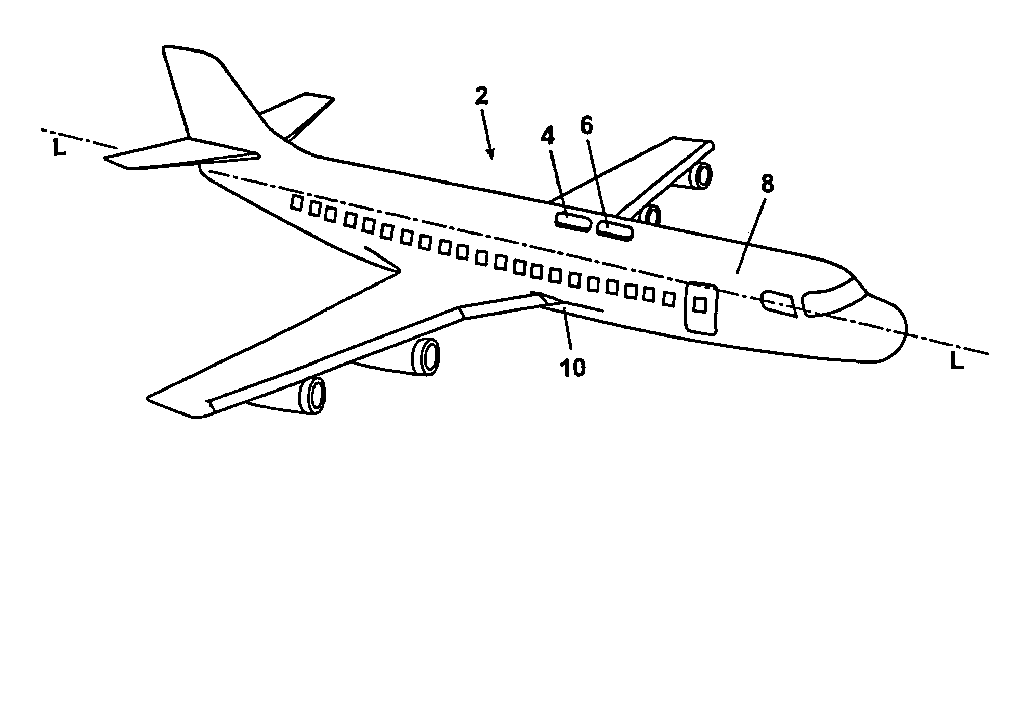
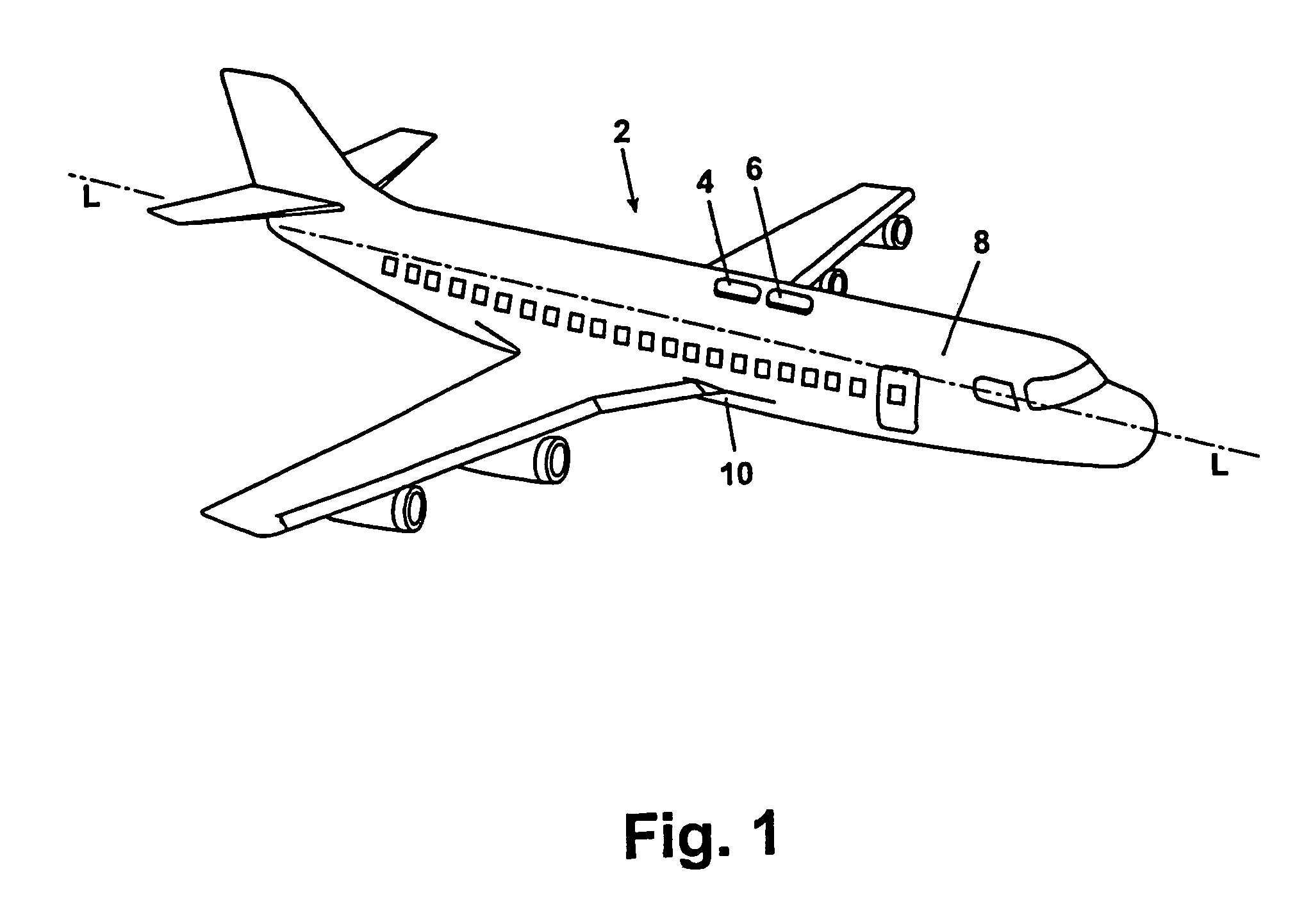
[0022]FIG. 1 provides transmit and receive antennas for one aspect of the present invention. An exemplary aircraft 2 is shown having an exemplary arrangement of two antennas, a transmit antenna 4 and a receive antenna 6 mounted on the outer aircraft fuselage 8. In a preferred embodiment both the external configurations of the transmit antenna 4 and receive antenna 6 have a tear-drop shape to minimize aerodynamic drag on the aircraft. The preferred location for the transmit and receive antennas is in a fore-aft, linear arrangement having both antennas located in parallel with a longitudinal axis L of the aircraft on an upper surface of the fuselage 8 and proximate to the fore-aft location along the longitudinal axis L where the leading edge of the aircraft wings 10 intersect the aircraft 2. The one or more antennas of the present invention are mounted directly to the outer fuselage 8 of the aircraft.

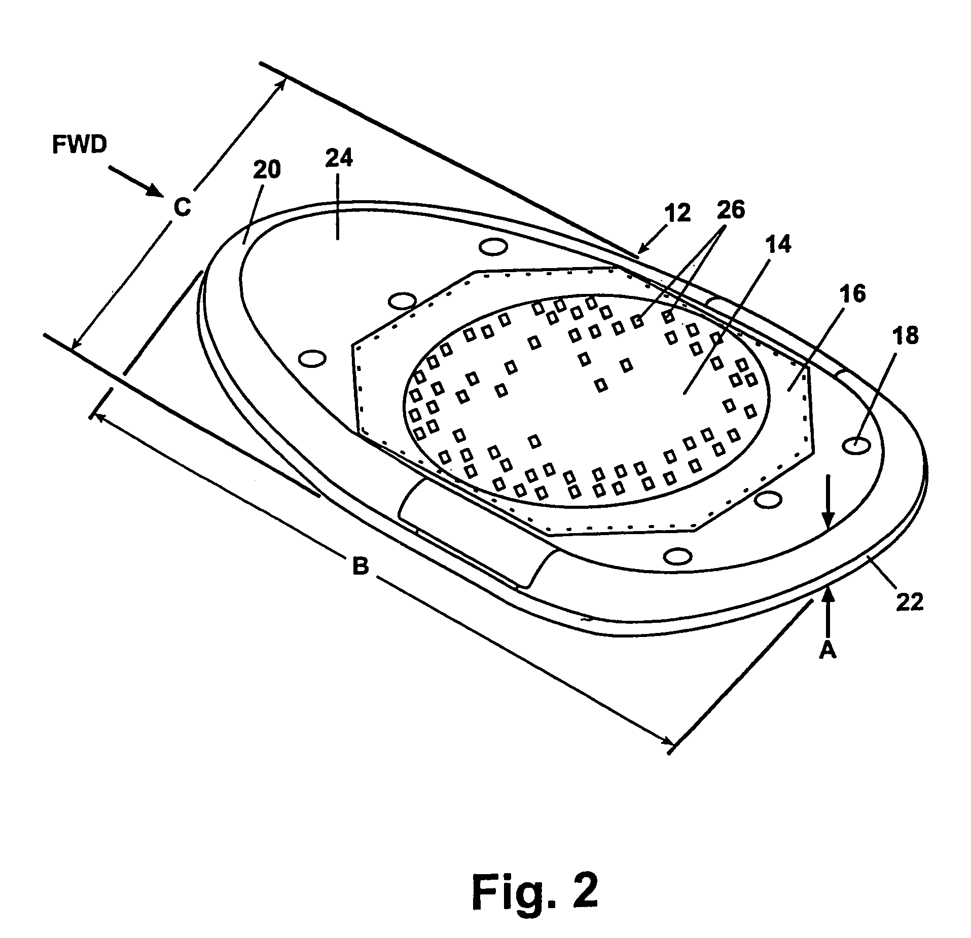
[0023]Referring now to FIG. 2, a tear-drop shaped antenna configuration for mounting ...


PUM


Abstract

An aircraft phased array antenna system has transmit and receive antenna structures externally mounted on the aircraft fuselage. Each antenna comprises a plurality of phased array elements and antenna power and support equipment. Aerodynamically shaping antenna structure to enclose an antenna element grid provides additional antenna structure volume, which is efficiently utilized by locating antenna support equipment within the antenna structure. To control signal attenuation a receive antenna internal converter converts receive frequency signals to L-band frequency signals for aircraft use, and a similar transmit antenna converter converts L-band frequency signals to transmit frequency signals, thus unconstraining antenna to internal aircraft equipment spacing. To reduce power loss and cabling weight, antenna operating power is first generated in the 28 to 270 volts DC range within the aircraft, and locally converted in each antenna to the 3 to 6 volt DC power to operate each antenna's phased array elements.

Description

CROSS-REFERENCE TO RELATED APPLICATIONS[0001]This application is a divisional application of U.S. patent application Ser. No. 10 / 057,286 filed on Jan. 25, 2002 now U.S. Pat. No. 6,844,855. The disclosure of the above application is incorporated herein by reference.FIELD OF THE INVENTION[0002]The present invention relates generally to aircraft antenna systems and more specifically to a phased array antenna system having both phased array antenna elements and antenna support equipment mounted within the antenna structure.BACKGROUND OF THE INVENTION[0003]Aircraft utilize antenna and associated antenna support equipment to transmit, receive and download data communication signals. Aircraft antenna(s) are typically surface mounted on the outer fuselage of the aircraft. Aerodynamic drag concerns require the antenna(s) be shaped to reduce drag on the aircraft. Associated equipment is normally located inside the aircraft on support structures developed for this purpose.[0004]When new system...

Claims


Application Information

Patent Timeline
Patent Type & Authority Patents(United States)
IPC IPC(8): H01Q1/28H01Q21/00
CPCH01Q1/286H01Q21/00
Inventor CARSON, RONALD S
Owner THE BOEING CO
Why Eureka
Try Eureka