Systems and methods for controlling illumination sources

a technology of illumination source and control system, applied in the direction of process and machine control, micro-instruction address formation, instruments, etc., can solve problems such as output changes

Inactive Publication Date: 2005-12-13
PHILIPS LIGHTING NORTH AMERICA CORPORATION
View PDF278 Cites 525 Cited by
  • Summary
  • Abstract
  • Description
  • Claims
  • Application Information

AI Technical Summary

Benefits of technology

[0049]The methods and systems disclosed herein also include methods and systems for providing a lighting control signal and may include methods and systems for providing a processor, providing memory, providing a light, providing a data input, providing a user interface, and using the processor to access a table stored in the memory to determine a control signal for the light, wherein the processor accesses the table to determine the control signal and wherein the table stores a nonlinear relationship between the data input and the control signal. The table can store a function that defines the nonlinear relationship. A user interface can allow a user to modify a parameter of the function, such as a PWM parameter and / or a scaling factor. In embodiments the user interface can allow a user to modify the table or select one or more tables from a plurality of tables. A function can define the relationship between the data input and the control signal, and can cause the ouput signal to increase continually in increasing amounts throughout the range of the data input.

Problems solved by technology

One of the problems with changing the apparent or actual light output of an LED from a low light level to a higher light level is that the output changes may appear as stepped function rather than a smooth transition.

Method used


Image

  • Systems and methods for controlling illumination sources
  • Systems and methods for controlling illumination sources
  • Systems and methods for controlling illumination sources

Examples


Embodiment Construction

)

[0057]The description below pertains to several illustrative embodiments of the invention. Although many variations of the invention may be envisioned by one skilled in the art, such variations and improvements are intended to fall within the compass of this disclosure. Thus, the scope of the invention is not to be limited in any way by the disclosure below.

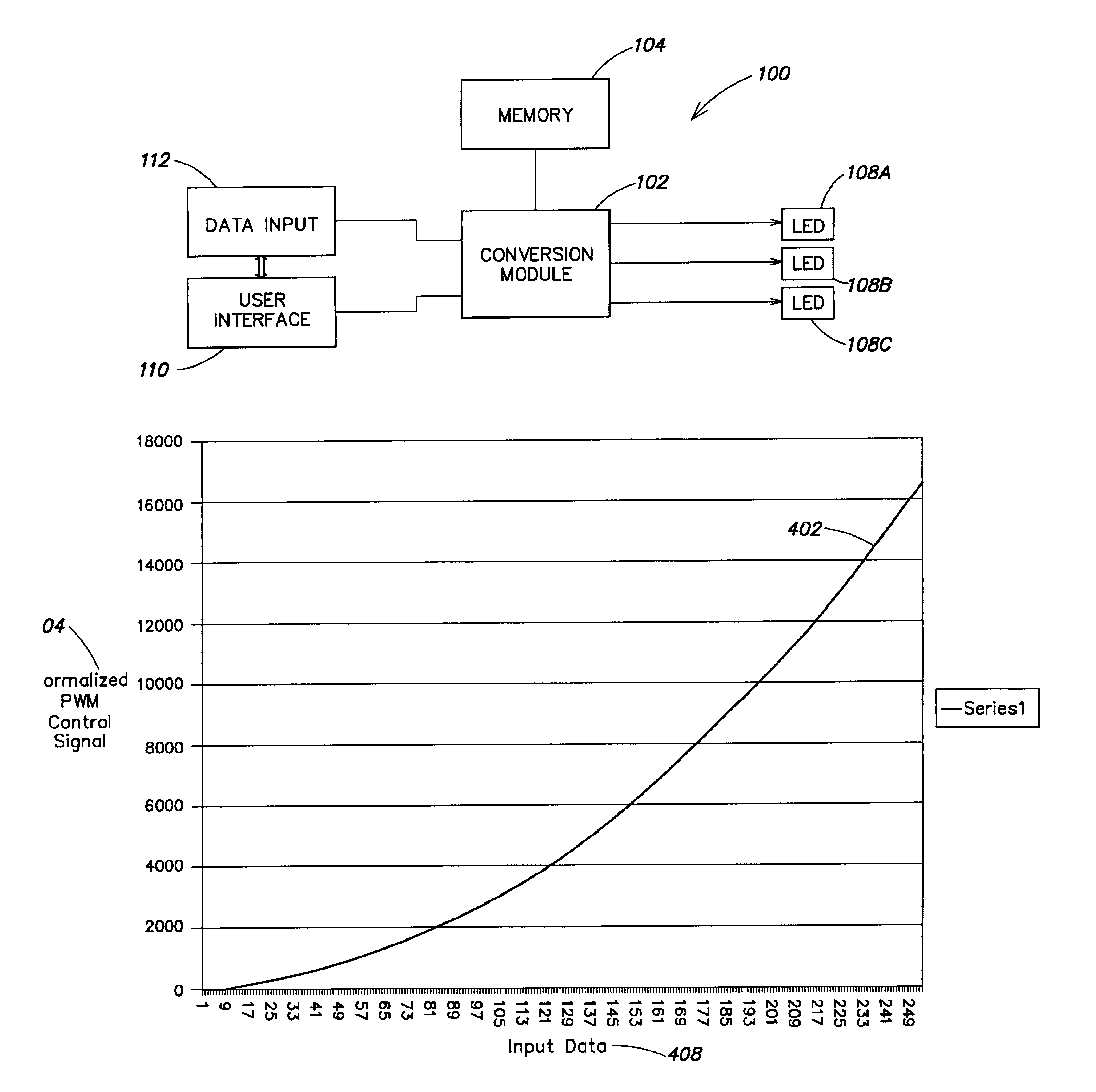
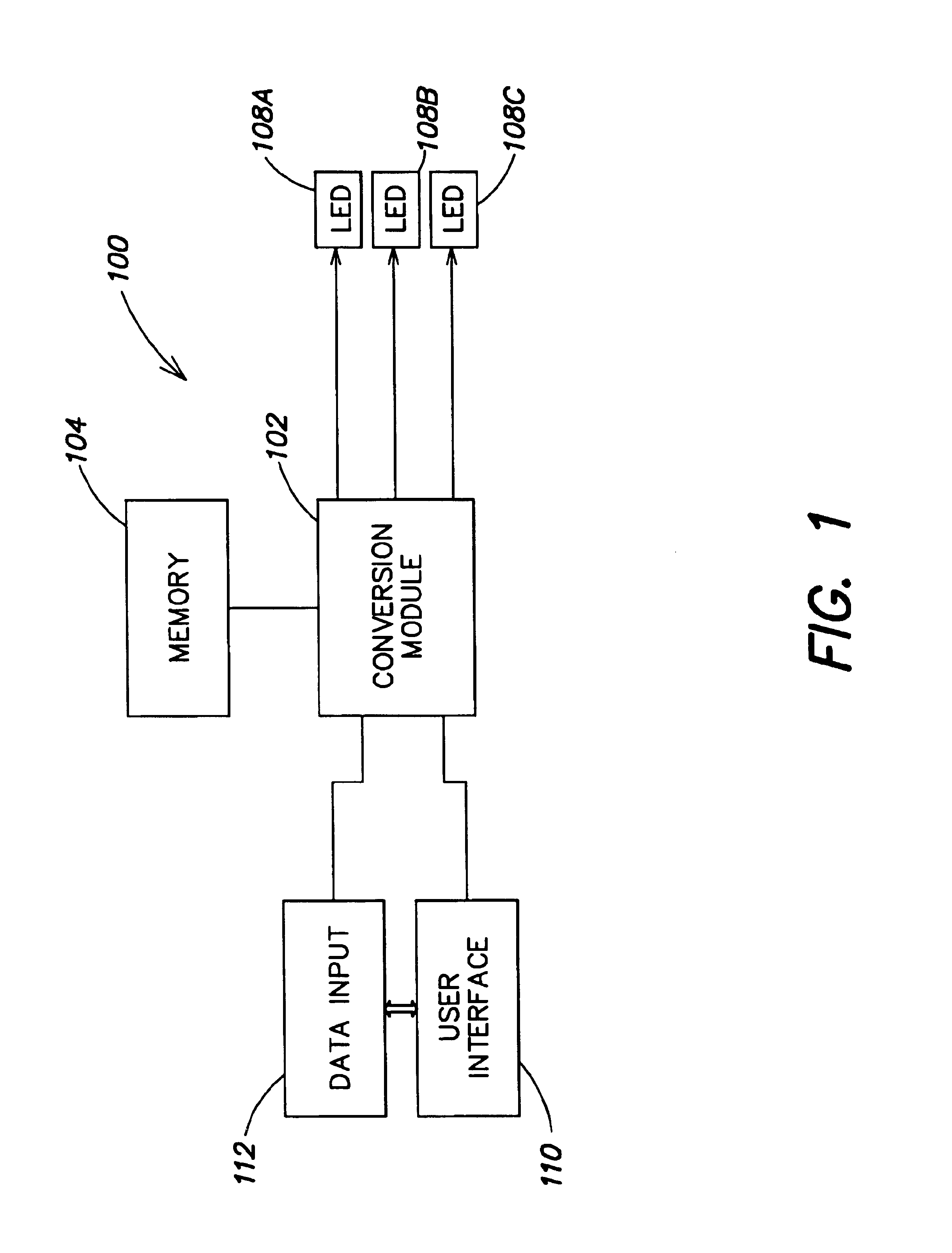
[0058]Referring to FIG. 1, in an embodiment, a lighting system 100 may generate light in response to control signals that are generated upon receipt of data. In embodiments the lighting system 100 includes one or more lights 108A, 108B, 108C, which may be LEDs of different colors, such as white, red, green, blue, amber, UV, IR or the like. In embodiments the LEDs 108 light at different intensities in response to control signals, currents, or the like, such as pulse width modulation (PWM) control signals. The lighting system 100 optionally has a data input 112. As data inputs 112, such systems may receive the data via a network, ...


PUM


Abstract

Provided are methods and systems for controlling the conversion of data inputs to a computer-based light system into lighting control signals. The methods and systems include facilities for controlling a nonlinear relationship between data inputs and lighting control signal ouputs. The nonlinear relationship may be programmed to account for varying responses of the viewer of a light source to different light source intensities.

Description

CROSS REFERENCE TO RELATED APPLICATIONS[0001]This application is based upon, claims priority to, and incorporates by reference a U.S. Provisional Patent Application Serial No. 60 / 298,471 entitled Systems and Methods for Controlling illumination Sources, filed Jun. 15, 2001, naming Ihor Lys, Frederick Morgan, Michael Blackwell and Alfred Ducharme as inventors.[0002]In addition, this patent application claims the benefit under 35 U.S.C. §119(e) of the following U.S. Provisional Applications:[0003]Serial No. 60 / 301,692, filed Jun. 28, 2001, entitled “Systems and Methods for Networking LED Lighting Systems”;[0004]Serial No. 60 / 328,867, filed Oct. 12, 2001, entitled “Systems and Methods for Networking LED Lighting Systems;” and[0005]Serial No. 60 / 341,476, filed Oct. 30, 2001, entitled “Systems and Methods for LED Lighting.”[0006]This application also claims the benefit under 35 U.S.C. §120 as a continuation-in-part (CIP) of U.S. Non-provisional application Ser. No. 09 / 971,367, filed Oct....

Claims


Application Information

Patent Timeline
Patent Type & Authority Patents(United States)
IPC IPC(8): G03B15/03G03B15/05G05F1/00
CPCG03B15/05G03B2215/05
Inventor LYS, IHOR A.MORGAN, FREDERICK M.BLACKWELL, MICHAEL K.DUCHARME, ALFRED D.
Owner PHILIPS LIGHTING NORTH AMERICA CORPORATION
Why Eureka
Try Eureka