

Control device for a medical system and control method for medical system
a control device and medical system technology, applied in the direction of electric controllers, ignition automatic control, instruments, etc., can solve the problems of cramped situations and occupying a great deal of space in the operating room
- Summary
- Abstract
- Description
- Claims
- Application Information
AI Technical Summary
Benefits of technology
Problems solved by technology
Method used
Image

Examples
first embodiment
[0051]A first embodiment of the present invention will be described with reference to FIG. 1 through FIG. 16G.
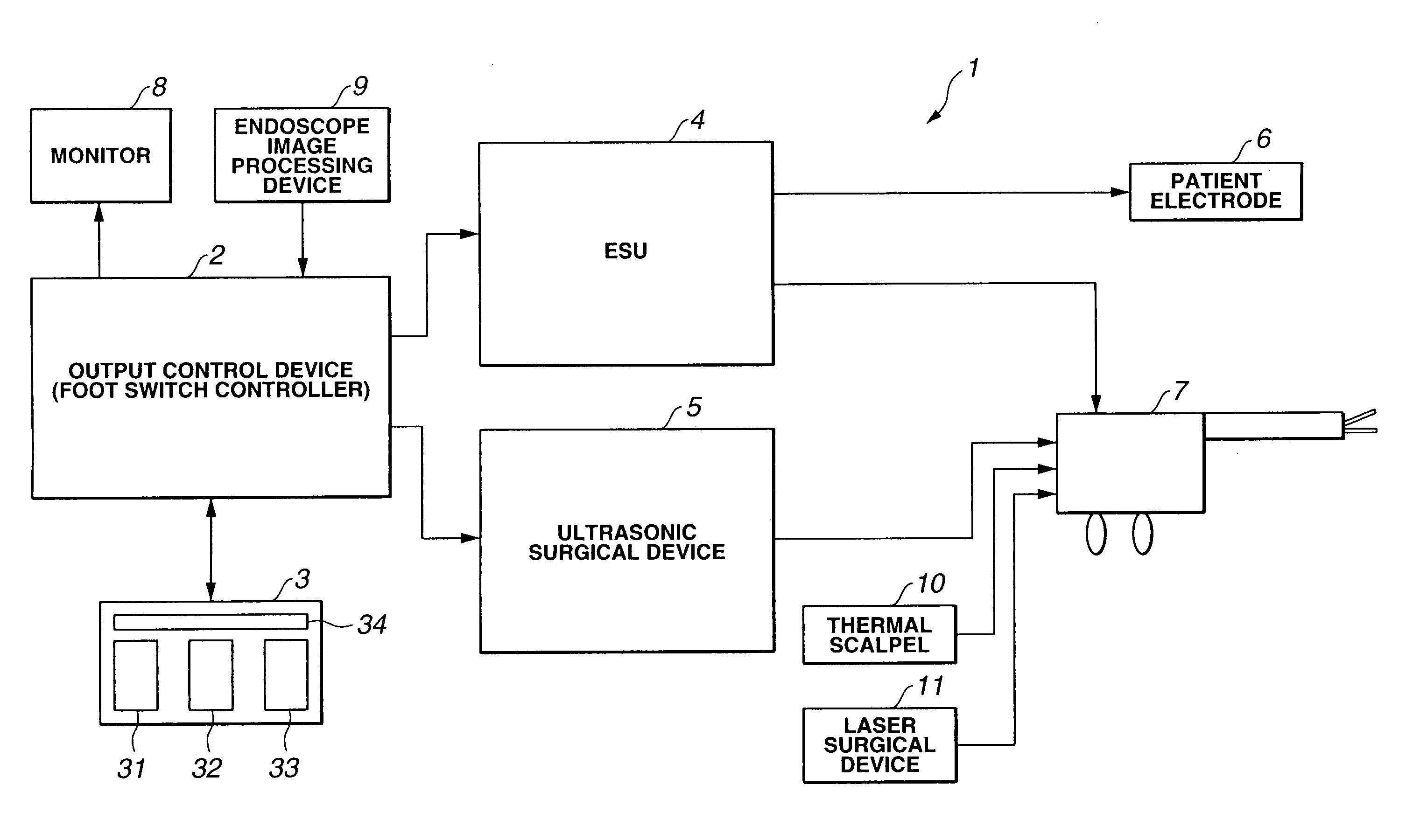
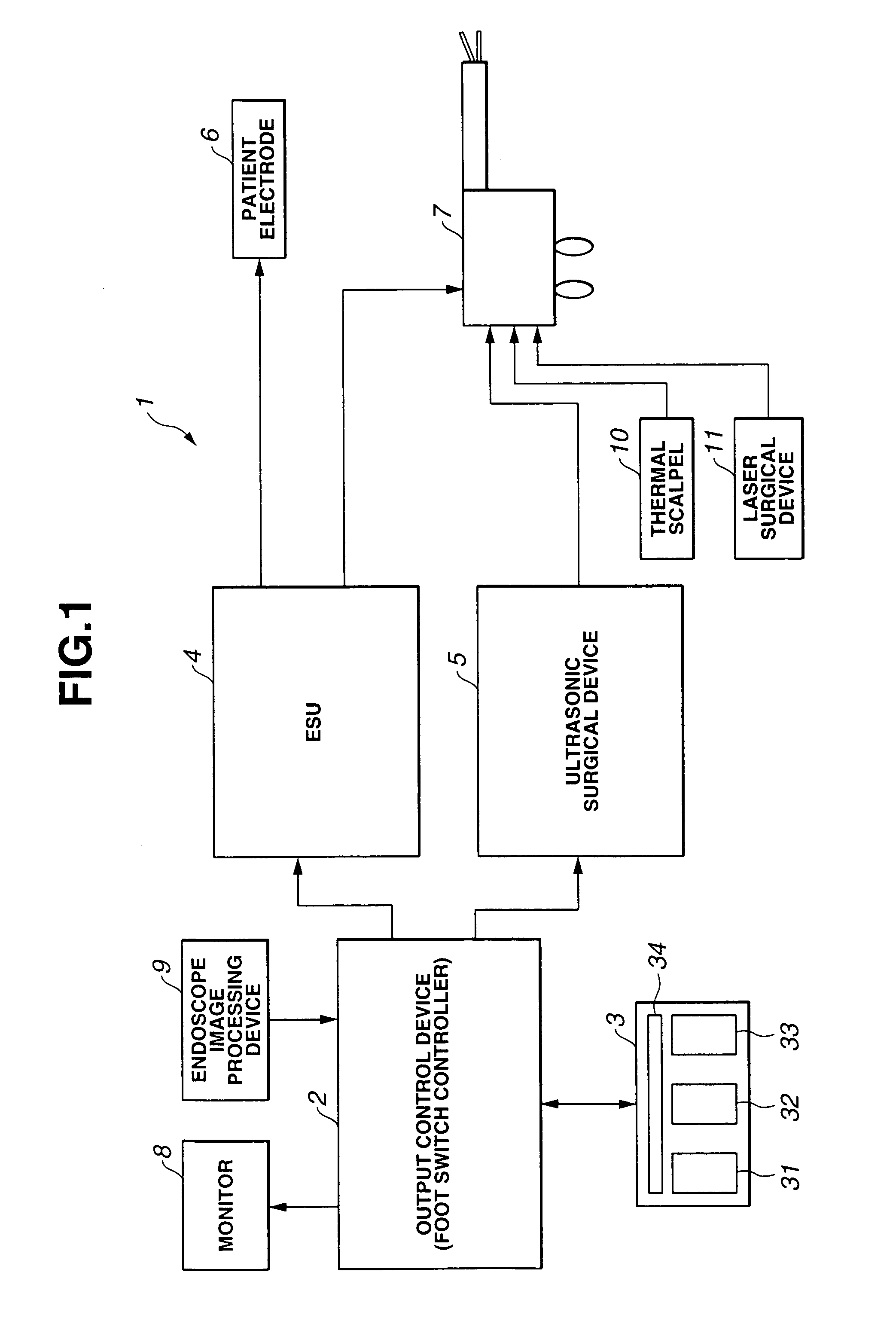
[0052]As shown in FIG. 1, a medical system 1 mainly comprises an output control device 2, a foot switch 3, an electric surgical device (otherwise known as an electrosurgical unit, hereafter, referred to as “ESU”) 4, an ultrasonic surgical device 5, a patient electrode 6, a handpiece 7, a monitor 8, an endoscope image processing device 9, a thermal scalpel 10, and a laser surgical device 11.
[0053]The output control device 2 is a control device for a medical system. The ESU 4, the ultrasonic surgical device 5, the thermal scalpel 10, and the laser surgical device 11 are medical apparatuses employed in the medical system 1.
[0054]The ESU 4 incises or coagulates an affected portion using a high-frequency current. An unshown high-frequency power output electrode for monopolar output provided on the ESU is connected to the handpiece 7 and the patient electrode 6. A power output ele...
second embodiment
[0162]Description will be made regarding a second embodiment of the present invention with reference to FIGS. 17 and 18. Note that in the description of the second embodiment using FIGS. 17 and 18, the same components as those in the first embodiment shown in FIGS. 1 thorough 16G will be denoted with the same reference numerals and the description thereof is omitted. With regard to the components of an endoscope system not shown in FIGS. 17 and 18, description will be made with reference to those of FIGS. 1 and 2.
Configuration
[0163]The output control device 2 according to the first embodiment shown in FIGS. 1 through 16G performs simultaneous output of the ESU 4 and the ultrasonic surgical device 5, and generates a control signal for each singular selection output, using integrated control of the computing unit 21.
[0164]An output control device 102 according to the second embodiment shown in FIG. 17 includes a timer circuit 130, an ESU output switch circuit 131, an ultrasonic surger...
third embodiment
[0194]Description will be made regarding a third embodiment of the present invention with reference to FIGS. 19 through 24. Note that in the description of the third embodiment using FIGS. 19 through 24, the same components as those in the first embodiment shown in FIGS. 1 thorough 16G will be denoted with the same reference numerals and the description thereof is omitted.
Configuration
[0195]As shown in FIG. 19, a medical system 201 according to the third embodiment detects which handpiece of the handpieces 211 and 212 of an ESU 204 and handpiece 213 of an ultrasonic surgical device 205, is held being and used by the operator, notifies the operator of the detected result, and then automatically maps the setting of the switch pedals of the foot switch 3, i.e., performs switch assignment in accordance with the detected result.
[0196]The medical system 201 according to the third embodiment, unlike that in the first embodiment, controls the ESU 204 and the ultrasonic surgical device 205 t...
PUM
 Abstract
Description
Claims
Application Information