Control system for internal combustion engine

a control system and internal combustion engine technology, applied in the direction of electrical control, process and machine control, instruments, etc., can solve the problems of affecting the efficiency of the engine, and the amount of fuel injected for the engine power output sometimes becomes too small or too large with respect to the intake air amount at the time, so as to improve the fuel economy and drivability.

Inactive Publication Date: 2007-04-05
HONDA MOTOR CO LTD
View PDF7 Cites 8 Cited by
  • Summary
  • Abstract
  • Description
  • Claims
  • Application Information

AI Technical Summary

Benefits of technology

[0007] It is a first object of the present invention to provide a control system for an internal combustion engine, which is capable of properly determining both a demanded combustion fuel amount for the engine power output and an auxiliary fuel amount for enabling a catalyst to exhibit its emission-reducing capability, as respective just enough amounts, during execution of auxiliary fuel supply, thereby making it possible to improve fuel economy and drivability, and cause the catalyst to properly exhibit its emission-reducing capability.
[0008] It is a second object of the present invention to provide a control system for an internal combustion engine, which is capable of obtaining a stable output torque of the engine, thereby improving drivability, even when supply of fuel to a cylinder over a predetermined time period within a time period from the expansion stroke through the exhaust stroke and EGR by an EGR device are concurrently carried out.
[0010] With the configuration of the control system according to the first aspect of the present invention, the whole demanded fuel amount-calculating means calculates the whole demanded fuel amount such that the concentration of oxygen in exhaust gases becomes equal to the predetermined oxygen concentration capable of controlling the catalyst to the predetermined state for causing the catalyst to exhibit its emission-reducing capability. Further, the demanded combustion fuel amount-determining means determines the demanded amount of combustion fuel to be supplied to the cylinder for the engine power output. The auxiliary fuel amount-determining means determines the amount of auxiliary fuel based on the difference between the whole demanded fuel amount and the demanded amount of combustion fuel (the demanded combustion fuel amount). Thus, the demanded combustion fuel amount for obtaining the engine power output is determined independently of the auxiliary fuel amount. Therefore, the demanded combustion fuel amount can be properly determined as a just enough amount without being adversely affected by the auxiliary fuel amount, and hence it is possible to improve fuel economy and drivability.
[0011] Further, since the auxiliary fuel is supplied to the cylinder over the predetermined time period within the time period from the expansion stroke through the exhaust stroke of the engine, the auxiliary fuel is not burned in the engine, but it is burned after being emitted from the engine together with exhaust gases generated by burning fuel for the engine power output. According to the first aspect of the present invention, the auxiliary fuel amount is determined based on the difference between the whole demanded fuel amount and the demanded combustion fuel amount calculated as above, and hence the total sum of the demanded combustion fuel amount and the auxiliary fuel amount is determined such that the concentration of oxygen in exhaust gases becomes equal to the predetermined oxygen concentration capable of controlling the catalyst to the predetermined state for causing the catalyst to exhibit its emission-reducing capability. This makes it possible to determine the auxiliary fuel amount as a just enough amount, and the oxygen concentration of exhaust gases generated by burning the demanded combustion fuel amount of fuel for the engine power output and the auxiliary fuel amount of fuel can be properly controlled to the predetermined oxygen concentration. This makes it possible to control the catalyst to the predetermined state, thereby making it possible to cause the catalyst to properly exhibit its emission-reducing capability.
[0016] As described above, the amount of the first supply fuel to be supplied to the cylinder for the engine power output is corrected according to the amount of additional fuel caused to be present in the cylinder by the EGR, and therefore it is possible to avoid a substantial increase in the amount of fuel burned in the engine by the amount of the additional fuel, thereby making it possible to properly control the amount of fuel burned in the engine. This makes it possible to obtain a stable output torque of the engine, even when the supply of fuel to the cylinder over the predetermined time period within the time period from the expansion stroke through the exhaust stroke and the EGR of the EGR device are concurrently carried out, whereby it is possible to improve drivability.
[0018] With this configuration of the preferred embodiment, the dynamic characteristic parameter-calculating means calculates the dynamic characteristic parameter indicative of the dynamic characteristics exhibited by the second supply fuel supplied to the cylinder until the second supply fuel is caused to be present in the cylinder, and the additional fuel amount-calculating means calculates the additional fuel amount based on the calculated dynamic characteristic parameter. This makes it possible to properly calculate the additional fuel amount in a fine-grained manner according to the actual behavior of the second supply fuel exhibited until it is caused to be present in the cylinder. Therefore, it is possible to obtain stable output torque of the engine and improve drivability more effectively.

Problems solved by technology

In the conventional control system, however, as described above, the ratio between the amount of fuel injected for the engine power output and the amount of fuel injected during the expansion stroke is determined according to the temperature required by the NOx catalyst and the engine speed, during execution of expansion stroke injection, and therefore the amount of fuel injected for the engine power output sometimes becomes too small or too large with respect to the intake air amount at the time.
In such a case, there is a fear that fuel economy is degraded during execution of expansion stroke injection, and the engine power output cannot be obtained, as desired, resulting in degraded drivability.
Further, when the conventional control system is combined with an EGR device for recirculating part of exhaust gases into the intake pipe of the engine, and expansion stroke injection and the exhaust gas-recirculating operation of the EGR device are performed concurrently, there occur the following inconveniences: In this case, part of unburned fuel caused to be contained in exhaust gases by expansion stroke injection flows into the cylinder after being recirculated into the intake pipe by the recirculating operation of the EGR device.
This causes a substantial increase in the amount of fuel burned in the cylinder.
The conventional control system only determines the total sum of the amount of fuel injected for the engine power output and the amount of fuel injected during the expansion stroke such that exhaust gases are made rich, so that if the amount of fuel burned in the cylinder substantially increases, the output torque of the engine can be fluctuated, resulting in degraded drivability.

Method used


Image

  • Control system for internal combustion engine
  • Control system for internal combustion engine
  • Control system for internal combustion engine

Examples


Embodiment Construction

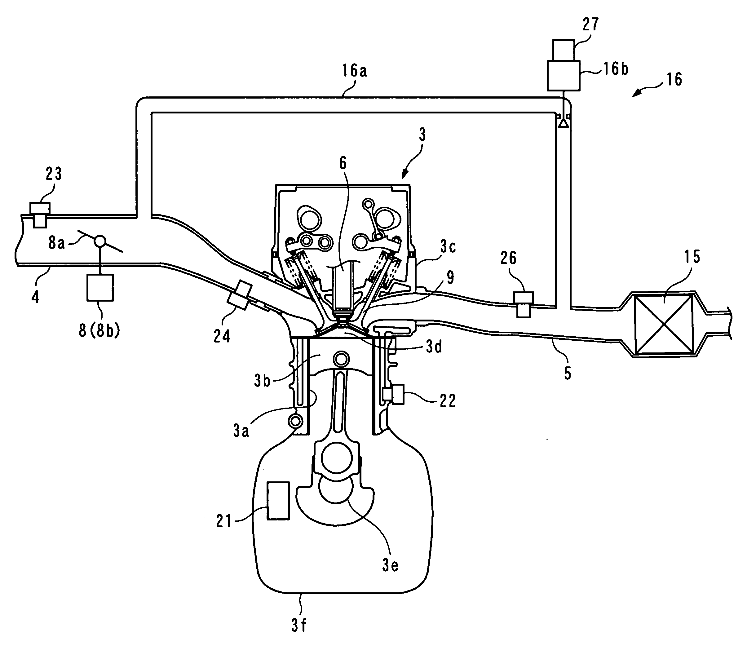
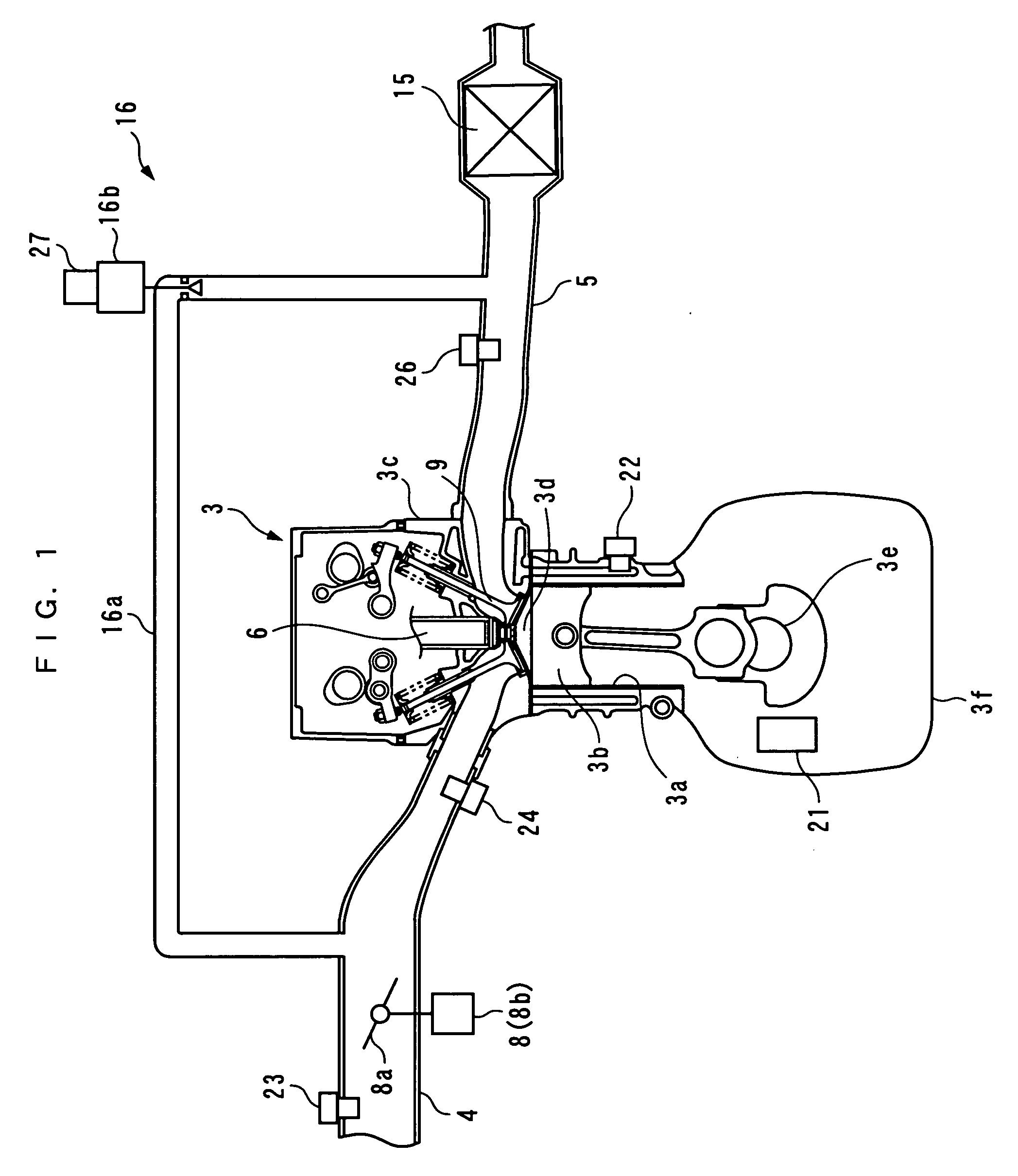
[0037] The present invention will now be described in detail with reference to the drawings showing a preferred embodiment thereof. Referring first to FIG. 1, there is schematically shown an internal combustion engine to which is applied a control system according to an embodiment of the present invention. The internal combustion engine (hereinafter simply referred to as “the engine”) 3 is e.g. an in-line four-cylinder gasoline engine installed on a vehicle, not shown.

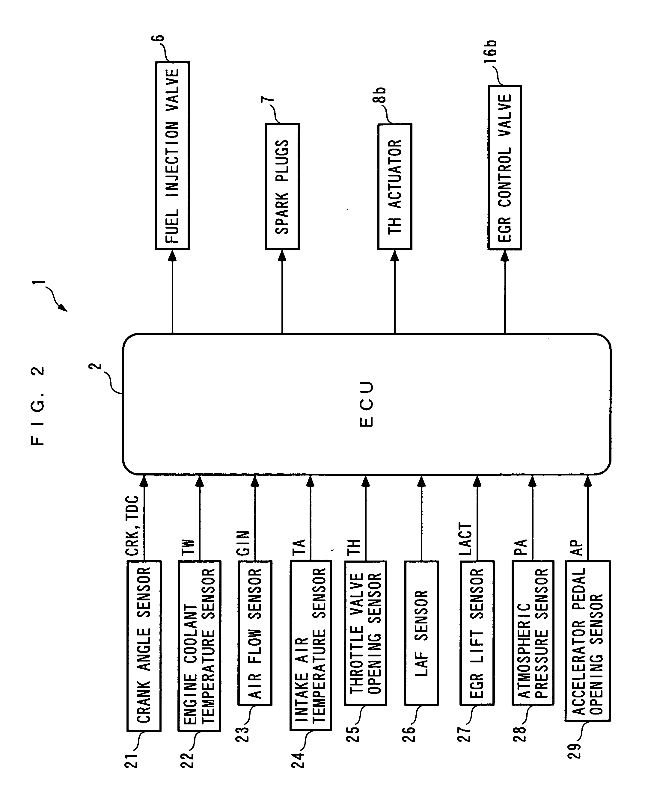
[0038] Defined between a piston 3b and a cylinder head 3c of each cylinder 3a is a combustion chamber 3d (only one set of these components is shown). Further, to the cylinder head 3c are connected an intake pipe 4 and an exhaust pipe 5, and a fuel injection valve (hereinafter referred to as “the injector”) 6 and a spark plug 7 (see FIG. 2) are mounted through the cylinder head 3c in a manner facing the combustion chamber 3d. The injector 6 is configured such that it directly injects fuel in the vicinity of the spark p...


PUM


Abstract

A control system for an internal combustion engine, which can determine just enough amounts of demanded combustion fuel and auxiliary fuel during execution of auxiliary fuel supply, for improvement of fuel economy and drivability and the emission-reducing capability of a catalyst. The control system carries out auxiliary fuel supply for a cylinder during a predetermined time period within the expansion and exhaust strokes, to control the catalyst to a predetermined state for its emission-reducing capability. The control system calculates a whole demanded fuel amount to make oxygen concentration in exhaust gases equal to a predetermined value for controlling the catalyst to the state during auxiliary fuel supply, determines the amount of demanded combustion fuel to be supplied to obtain engine output, and determines the auxiliary fuel amount based on the difference between the whole demanded fuel amount and the demanded combustion fuel amount.

Description

BACKGROUND OF THE INVENTION [0001] 1. Field of the Invention [0002] This invention relates to a control system for an internal combustion engine, which carries out auxiliary fuel supply for supplying fuel to a cylinder as auxiliary fuel over a predetermined time period within a time period from an expansion stroke through an exhaust stroke of the engine, so as to control a catalyst for reducing exhaust emissions to a predetermined state for causing the catalyst to exhibit its emission-reducing capability, and a control system for an internal combustion engine, which supplies fuel to a cylinder and performs EGR for causing part of combustion gases generated by combustion to be present in the cylinder, by an EGR device. [0003] 2. Description of the Related Art [0004] Conventionally, a control system of the first-mentioned kind has been disclosed in Japanese Laid-Open Patent Publication (Kokai) No. H11-107813. The internal combustion engine is of an in-cylinder injection type for direc...

Claims


Application Information

Patent Timeline
Patent Type & Authority Applications(United States)
IPC IPC(8): F01N3/00F01N3/10
CPCF02D41/0065F02D41/0245F02D41/3029F02D41/3076F02D41/405Y02T10/44Y02T10/26Y02T10/47Y02T10/12Y02T10/40
Inventor OGAWA, KENSHINOHARA, TOSHINARINAKANO, TETSUAKI
Owner HONDA MOTOR CO LTD
Why Eureka
Try Eureka