Method and system for determining final desired wheel power in a hybrid electric vehicle powertrain

a hybrid electric vehicle and powertrain technology, applied in vehicle position/course/altitude control, process and machine control, instruments, etc., can solve problems such as unwound power clipping

Active Publication Date: 2009-11-17
FORD GLOBAL TECH LLC
View PDF33 Cites 61 Cited by
  • Summary
  • Abstract
  • Description
  • Claims
  • Application Information

AI Technical Summary

Benefits of technology

[0008]Inaccuracies in wheel power determination during both transient operation and steady state operation of the powertrain are avoided by the method and system of the invention. The invention, which includes a vehicle system controller, modifies the portion of the wheel power supplied by the battery using a profiling technique such that battery charge and discharge limits are not violated when a change in power at the vehicle wheels is demanded by a driver. If, for example, a driver demand for power is increased during a so-called transient tip-in acceleration event following steady state operation of the powertrain, the demand for battery power will increase at the instant a tip-in is made. The control system at that instant will undertake a profiling calculation of the final wheel power and desired battery power. Without the profiling feature of the invention, the desired battery power will tend to spike instantaneously to an overshoot value above the desired battery power. The spike would be followed by an instantaneous undershoot spike in the calculated desired battery power below the desired battery power. A fluctuation from the peak value to the lower value would be followed by continued fluctuations in the calculated desired battery power until a desired battery power finally is reached in a moderating fashion as the driver demand for power at the wheels is reached.
[0009]The profiling feature of the invention will prevent uncontrolled, instantaneous spikes in the desired battery power calculation. This profiling will ensure that battery discharge power limits and battery charging power limits are not exceeded during instantaneous spikes in the desired battery power that would occur without profiling. Profiling improves drivability during both steady state powertrain operation and transient powertrain operation.
[0012]According to a second embodiment of the invention, the system will avoid allowing fluctuations or perturbations in the actual engine power to affect the profiled battery power used for wheel power determinations when the desired battery power is greater than battery charge power limits and less than battery discharge power limits. It does this by eliminating the effect of actual engine power fluctuations or perturbations from the calculation of a battery power profiling modifier. This is accomplished by adding actual engine power to a desired battery power before profiling occurs. After profiling is done, actual engine power is subtracted from the profiled driver demand for power. That value then is subtracted from the desired battery power in a determination of a battery power modifier used in a final desired wheel power determination.

Problems solved by technology

Wheel power clipping is not desired when desired wheel power calculations are made during a transient event if battery power limits would be exceeded only because of the power spikes.

Method used


Image

  • Method and system for determining final desired wheel power in a hybrid electric vehicle powertrain
  • Method and system for determining final desired wheel power in a hybrid electric vehicle powertrain
  • Method and system for determining final desired wheel power in a hybrid electric vehicle powertrain

Examples


Embodiment Construction

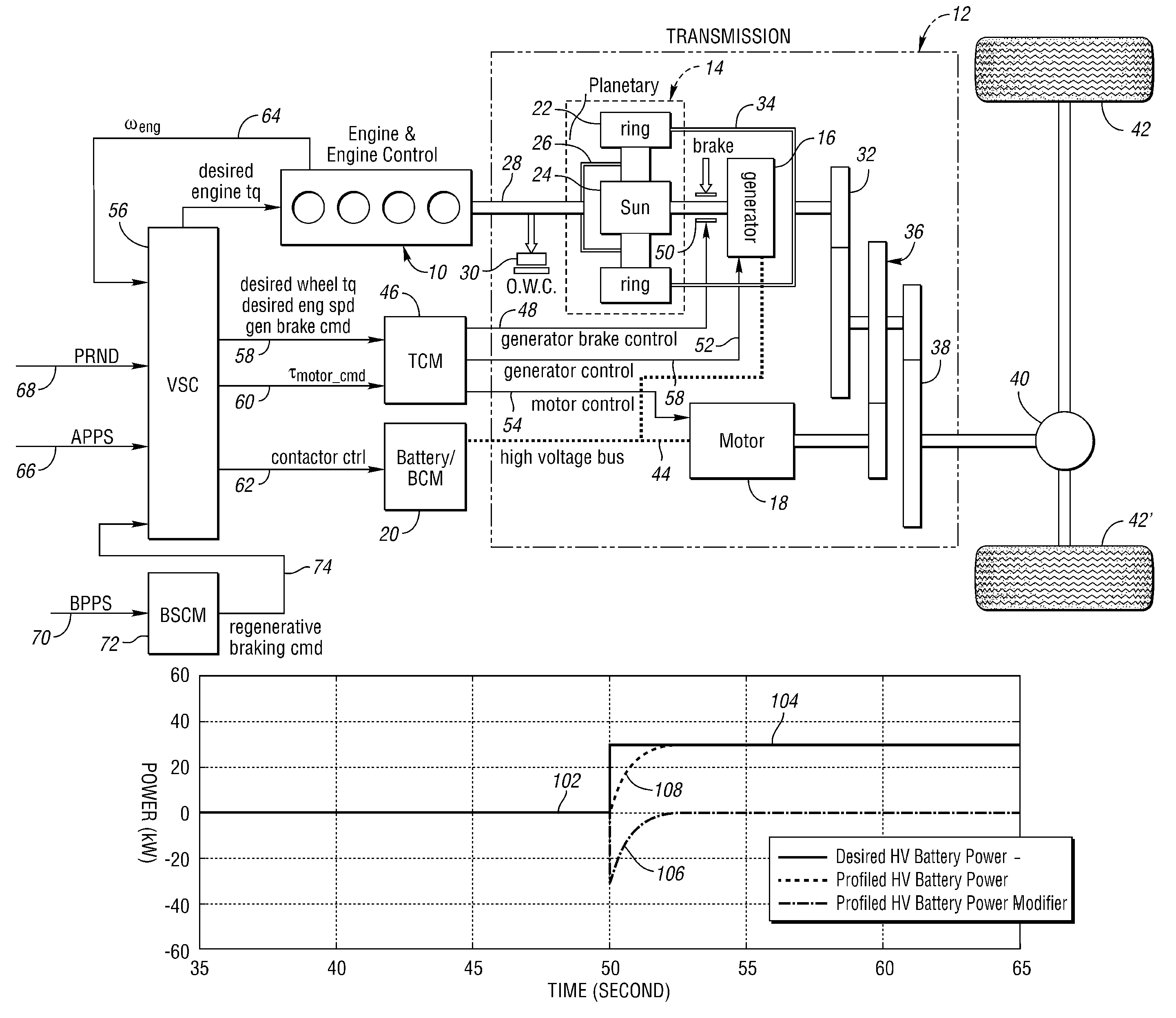
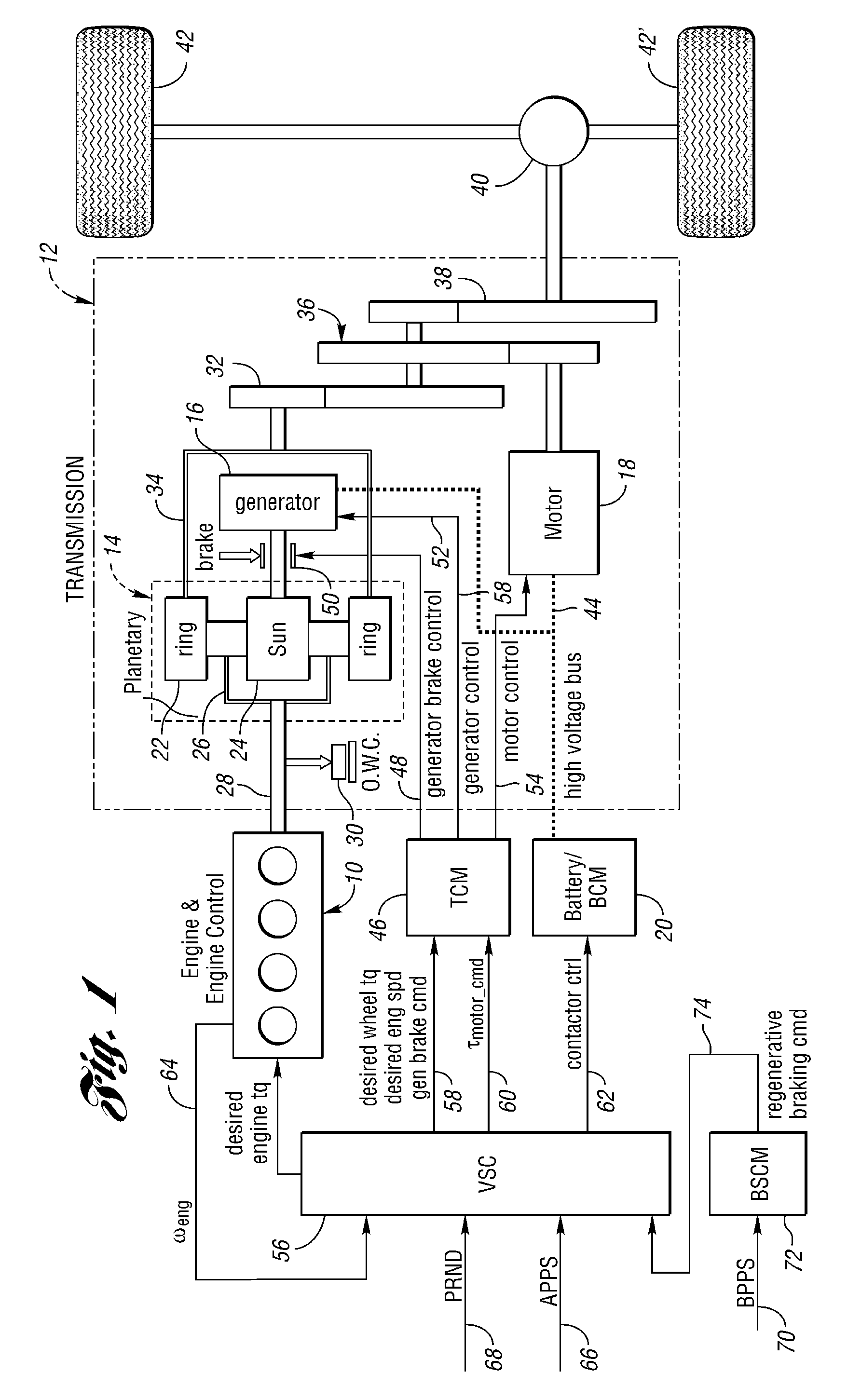
[0025]FIG. 1 shows a power split hybrid electric vehicle powertrain, which has parallel power flow paths from two power sources to vehicle traction wheels. One power source is an internal combustion engine and the other power source is a generator / motor / battery system. The power flow paths are defined in part by gearing, the engine being connected to one element of the gearing and the generator of the generator / motor / battery system being connected to another element of the gearing.

[0026]Although the powertrain schematically illustrated in FIG. 1 is capable of embodying the invention, the invention also could be used in any of a variety of other hybrid electric vehicle powertrains in which an engine power source and an electric power source are used to establish simultaneous power delivery to vehicle traction wheels.

[0027]In the embodiment of FIG. 1, numeral 10 generally designates an engine and an engine control, and numeral 12 generally designates a transmission, which includes pla...


PUM


Abstract

A control method and system for a hybrid electric vehicle powertrain is disclosed. A filtered, profiled battery power modifier is used in calculating a final desired wheel power. Unstable battery power oscillations are avoided when a change in driver power demand is made. The effect of engine torque disturbances also is avoided during steady state operation when desired battery power is between limiting charge or discharge values.

Description

CROSS-REFERENCE TO RELATED APPLICATIONS[0001]This application is based upon U.S. provisional application Ser. No. 60 / 704,648, filed Aug. 2, 2005. Applicants claim the priority of that provisional application.BACKGROUND OF THE INVENTION[0002]1. Field of the Invention[0003]The invention relates to a method and system for controlling a hybrid electric vehicle powertrain to maintain battery charging power and battery discharging power within predetermined power limits.[0004]2. Background Discussion[0005]In a typical hybrid electric vehicle powertrain for contemporary automotive vehicles, there are at least two power sources. One power source is an engine, such as an internal combustion engine, and a second source is an electric motor-generator system. A battery, which is a part of the motor-generator system, acts as an energy storing medium. The power sources may operate simultaneously to meet a driver demand for torque at the traction wheels of the vehicle. Examples of powertrains of t...

Claims


Application Information

Patent Timeline
Patent Type & Authority Patents(United States)
IPC IPC(8): B60K6/20B60K6/445
CPCB60K6/445B60W20/102B60W10/26Y02T10/6239B60W20/11Y02T10/62
Inventor SYED, FAZALKUANG, MINGCZUBAY, JOHNSMITH, MATTHEWOKUBO, SHUNSUKE
Owner FORD GLOBAL TECH LLC
Why Eureka
Try Eureka