Method and apparatus for determination of the state-of-charge (SOC) of a rechargeable battery

a rechargeable battery and state-of-charge technology, which is applied in the field of method for determining the state-of-charge (soc) of a rechargeable battery, can solve the problems of inability to include all relevant battery behaviour in the look-up table or function, method cannot work during external current flow or after current flow before the battery voltage has fully relaxed, etc., to achieve the effect of improving adaptability accuracy

Inactive Publication Date: 2010-02-25
KONINKLIJKE PHILIPS ELECTRONICS NV
View PDF5 Cites 29 Cited by
  • Summary
  • Abstract
  • Description
  • Claims
  • Application Information

AI Technical Summary

Benefits of technology

[0032]This method and apparatus provide a novel way of modelling wherein the inaccuracy inherent to inverted functions is avoided. Further the model can be adapted to the measuring results by adaptation of the parameters. The advantage is that no numerical inversion is used such as the prior art methods do. This advantage makes the method easier to adapt and to implement on a portable application than the prior art EMF=f(SoC) methods.
[0037]With the SoC1 function described by Eq. 9 the remaining run-time in point B can be predicted directly after discharging has started in point A (see FIG. 2). The function contains a set of parameters that are found by fitting on available SoC1 measured values. The advantages are (i) that SoC1 is easy to be measured (see FIG. 2) (ii) that no prediction of the overpotential, voltage measurement and EMF model calculation are necessary under load conditions and (iii) the remaining run-time is directly calculated with one function. The first advantage improves the patented remaining run-time indication algorithm, since it enables more accuracy in the SoC1 calculation. The second advantage eliminates the need of overpotential prediction, voltage measurement and EMF model calculation under load conditions. The third advantage reduces the number of measurements and calculations for the remaining run-time prediction when compared with the prior-art remaining run-time prediction methods.
[0044]In order to deal with the aging effect and to improve the SoC calculation accuracy new adaptive and predictive methods have been developed as disclosed by WO2005085889. For instance, the system disclosed in this document adapts the battery maximum capacity and the battery overpotential model parameters to take the aging effect into account. In this adaptive method, the maximum capacity can be updated without the necessity to impose a full charge / discharge cycle on the battery. Provided that starting from a state of equilibrium, the battery is charged or discharged for a certain minimum amount of charge, after which the battery returns to equilibrium, the maximum capacity can simply be calculated by relating the difference in SoC [%] before and after the charge or discharge step to the absolute amount of charge in [C] discharged from or charged to the battery during the applied charge / discharge step. Existing systems always have to apply a full charge / discharge cycle to determine the maximum available battery capacity. The adaptive method referred to above uses also a ratio between the measured charge overpotential for an aged and for a fresh battery (ηcha / ηchf) and the overpotential symmetry phenomenon in order to adapt the overpotential model parameters with the aging effect. The voltage-prediction method has further extended the EMF and maximum capacity methods usability during the relaxation process also. As a result, the calibration and adaptation possibilities of the SoC algorithm have been improved.
[0059]It follows from FIGS. 7 and 8 that a maximum EMF difference of 36 mV is retrieved at 1.1% SoC. This means that when using the EMF adaptation method the SoC indication system based on EMF will display an SoC value of 1.3% in this case when the actual SoC value calculated based on the discharge EMF is 1.1%. The inaccuracy will be −0.2% SoC. This effect will be more pronounced in the flat region of the EMF-SoC curve where even small differences in EMF will cause larger errors in SoC. For instance, a difference of about 8 mV is retrieved at 67% SoC. In this case the EMF adaptation method leads to an inaccuracy of 1% SoC. It can be concluded from FIGS. 7 and 8 and the situations described above that the newly developed EMF adaptation method will offer an always better than 1% SoC accuracy even when only 10 predicted EMF points after 15 minutes of relaxation are used to build the new EMF curve for an aged battery. The EMF adaptation accuracy can be easily improved by considering a longer relaxation time periods for the voltage-relaxation model or more EMF points for the fitting method.

Problems solved by technology

The main disadvantage of this group of methods is that it is very hard to include all relevant battery behaviour in the look-up table or function.
This leads to inaccuracy of the predicted SoC.
However, this method does not work during external current flow or after current flow before the battery voltage has fully relaxed, since the battery terminal voltage does not equal the EMF in this case.
Unfortunately, this is not the case.
For example, stored charge is not available to the user under all conditions, e.g. due to diffusion limitations, and battery charge will slowly decrease when the battery is not in use due to self-discharge.
The main disadvantages are (i) that the system needs to be connected to the battery at all times, (ii) the fact that upon first connection the system does not know the SoC (the starting point of integration has to be programmed) and (iii) the need for calibration points.
One of the main drawbacks of this method is that even in the case of a single battery type it is impossible to take into account every point of the EMF curve in order to provide an accurate SoC indication system.
Even if many measurement points are included, the process becomes more complicated and expensive than other approaches and probably does not provide any significant advantages.
This leads numerical calculations that may decrease the SoC calculation accuracy.
However, after 37.3 minutes the battery reached the level of 3 V. This means that the inaccuracy of the SoC system is 10.2 minutes in remaining run-time.

Method used


Image

  • Method and apparatus for determination of the state-of-charge (SOC) of a rechargeable battery
  • Method and apparatus for determination of the state-of-charge (SOC) of a rechargeable battery
  • Method and apparatus for determination of the state-of-charge (SOC) of a rechargeable battery

Examples


Embodiment Construction

[0078]As described in the previous sections the newly proposed SoC=f(EMF) and SoC1 models can be used advantageously in the prior SoC indication algorithm. However, it can also be used in any SoC system in which the EMF of the battery is used to determine the SoC and that indicates the remaining run-time as well.

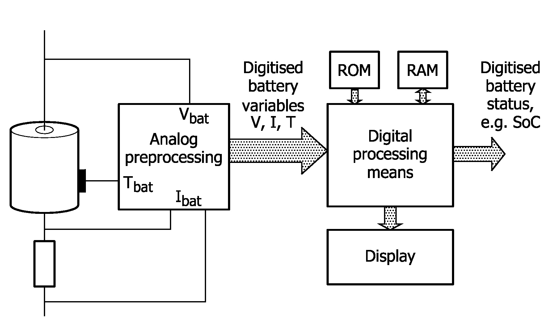
[0079]FIG. 10 shows a general block diagram of how the SoC=f(EMF) and SoC1 methods may be implemented in an SoC indication system. The battery voltage Vbat, current Ibat and temperature Tbat are measured by means of an analog pre-processing unit, including e.g. filtering, amplification and digitisation. Digital representations of the battery variables are fed to a digital processing means, such as a micro-controller. SoC=f(EMF) and SoC1 methods as well as any SoC-indication system based on the EMF method runs on this digital processing unit. The unit also makes use of memory, which can be external memory or memory present on the same silicon die. ROM memory is used to store ...


PUM


Abstract

The present invention relates to a method for determination of the state-of-charge (SoC) of a rechargeable battery as a function of the Electro-Motive Force (EMF) prevailing in said battery. The invention also relates to a method for measuring the relation between the state-of-charge (SoC) and the EMF. The invention further relates to an apparatus for determination of the State-of-Charge (SoC) of a rechargeable battery as a function of the Electro-Motive Force (EMF) prevailing in said battery.

Description

FIELD OF THE INVENTION[0001]The present invention relates to a method for determination of the state-of-charge (SoC) of a rechargeable battery as a function of the Electro-Motive Force (EMF) prevailing in said battery. The invention also relates to a method for measuring the relation between the state-of-charge (SoC) and the EMF. The invention further relates to an apparatus for determination of the State-of-Charge (SoC) of a rechargeable battery as a function of the Electro-Motive Force (EMF) prevailing in said battery.BACKGROUND OF THE INVENTION[0002]Accurate and reliable State-of-Charge (SoC) indication is an important feature on any device powered by rechargeable batteries. With an accurate and reliable SoC indication a user will use all available battery capacity, which will prevent unnecessary recharges that would lead to even more battery wear-out. Numerous methods for SoC indication have been published and patented. Basically, these methods can be divided over two groups, i....

Claims


Application Information

Patent Timeline
Patent Type & Authority Applications(United States)
IPC IPC(8): H02J7/00G01R31/36
CPCG01R31/3651G01R31/362G01R31/367G01R31/3835
Inventor BERGVELD, HENDRIK JOHANNESPOP, VALERNOTTEN, PETRUS H.L.
Owner KONINKLIJKE PHILIPS ELECTRONICS NV
Why Eureka
Try Eureka