Power output apparatus and hybrid vehicle equipped with power output apparatus

a technology of power output apparatus and hybrid vehicle, which is applied in the direction of engine-driven generators, transportation and packaging, and generating power, etc., can solve the problems of unsuitable vehicle mounting, unsuitable electrical drive system, and difficult application of power output apparatus, so as to improve power transmission efficiency, wide drive range, and enhance fuel efficiency

Inactive Publication Date: 2010-04-13
TOYOTA JIDOSHA KK
View PDF7 Cites 64 Cited by
  • Summary
  • Abstract
  • Description
  • Claims
  • Application Information

AI Technical Summary

Benefits of technology

[0019]The power output apparatus mounted on the hybrid vehicle is downsized to be especially suitable for the vehicle having a rear wheel drive system as a main drive system and is arranged to improve the power transmission efficiency in a wide drive range. The hybrid vehicle according to the above aspect of the invention accordingly has the enhanced fuel efficiency and the improved driving performance.

Problems solved by technology

Because of the limited space for mounting the power output apparatus, there is a difficulty in application of the power output apparatus in the Patent Document 1 mentioned above to a vehicle having a rear wheel-drive system as a main drive system, that is, a rear wheel-drive vehicle or a rear wheel drive-based four wheel drive vehicle.
The parallel shaft-type transmission, however, has rather large dimensions both in an axial direction and in a radial direction and is thus not suitable for mounting on the vehicle.
The power output apparatus in the Patent Document 2 also requires a rotor of a large diameter and thereby causes its electrical drive system to be rather bulky and unsuitable for mounting on the vehicle.
Therefore, the power output apparatus in the Patent Document 2 has the low possibility for the practical application.

Method used


Image

  • Power output apparatus and hybrid vehicle equipped with power output apparatus
  • Power output apparatus and hybrid vehicle equipped with power output apparatus
  • Power output apparatus and hybrid vehicle equipped with power output apparatus

Examples


Embodiment Construction

[0034]One mode of carrying out the invention is discussed below as a preferred embodiment.

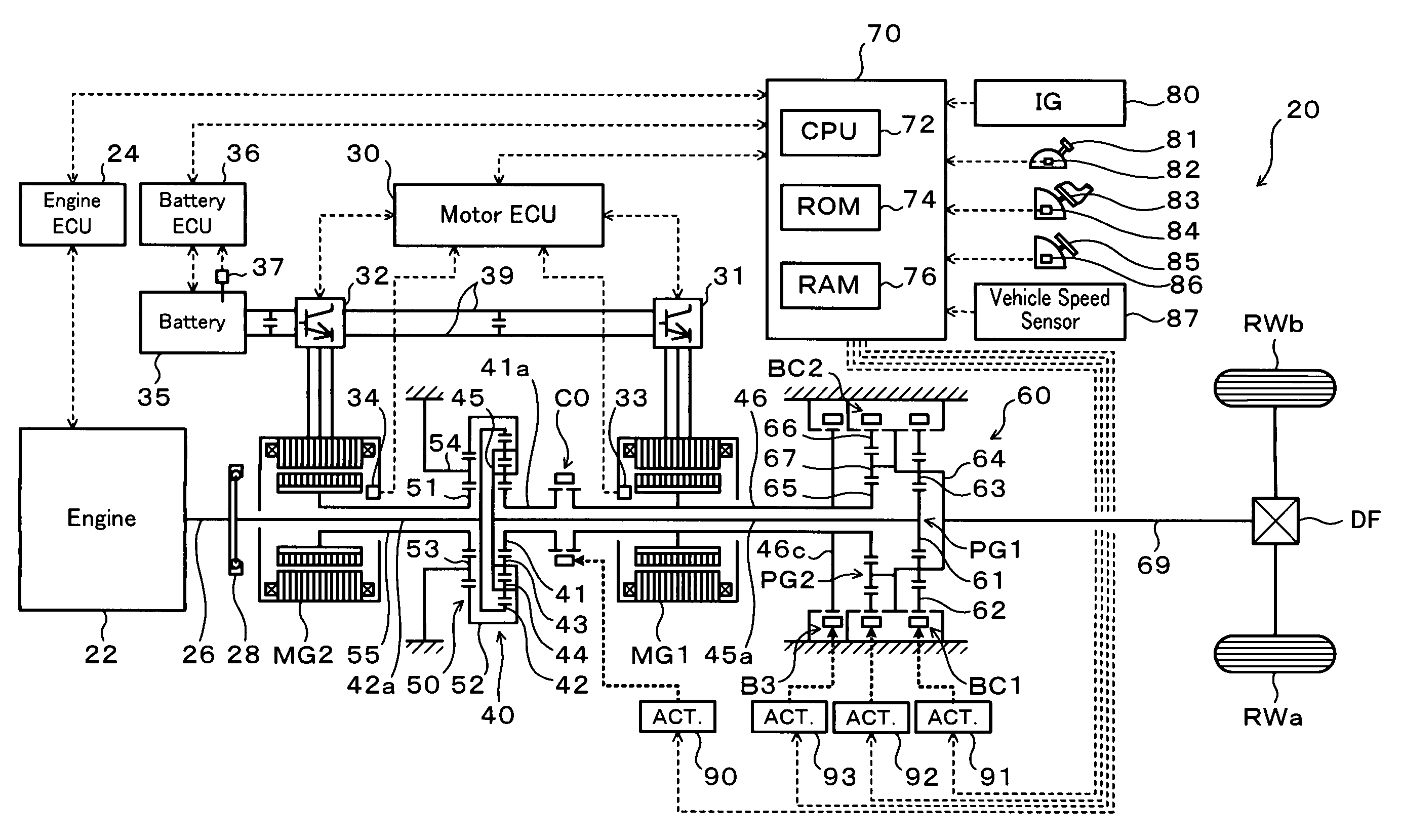
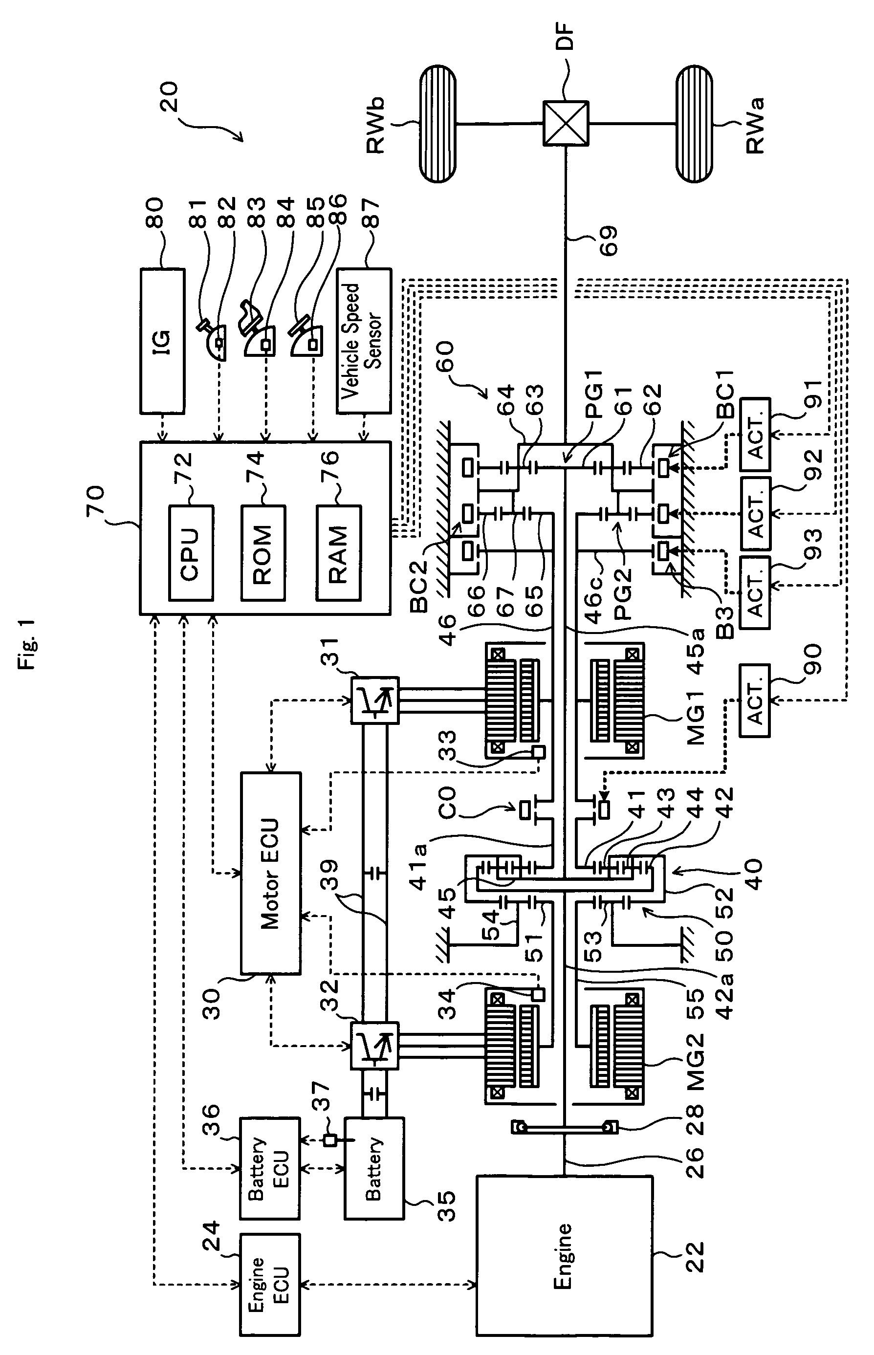
[0035]FIG. 1 schematically illustrates the configuration of a hybrid vehicle 20 equipped with a transmission 60 as a power transmission mechanism in one embodiment of the invention. The hybrid vehicle 20 shown in FIG. 1 is constructed as, for example, a rear-wheel drive vehicle and includes an engine 22 located in a front portion of the vehicle body, a power distribution integration mechanism 40 connected to a crankshaft (engine shaft) 26 of the engine 22, a motor MG1 linked with the power distribution integration mechanism 40 and arranged to have power generation capability, a motor MG2 linked with the power distribution integration mechanism 40 via a reduction gear mechanism 50 and arranged to be coaxial with the motor MG1 and have power generation capability, a transmission 60 arranged to convert the output power of the power distribution integration mechanism 40 and transmit the converted p...


PUM


Abstract

A hybrid vehicle 20 of the invention is equipped with a power distribution integration mechanism 40 and a transmission 60. The power distribution integration mechanism 40 includes a carrier 45 connecting with a motor MG2, a sun gear 41 connecting with a motor MG1, and a ring gear 42 connecting with an engine 22. The transmission 60 includes a first change speed planetary gear mechanism PG1, a second change speed planetary gear mechanism PG2, a brake clutch BC1 configured to fix a ring gear 62 of the first change speed planetary gear mechanism PG1 in a non-rotatable manner and release the ring gear 62 in a rotatable manner and to couple the ring gear 62 with a common carrier 64 shared by the first change speed planetary gear mechanism PG1 and the second change speed planetary gear mechanism PG2, and a second brake clutch BC2 configured to fix a ring gear 66 of the second change speed planetary gear mechanism PG2 in a non-rotatable manner and release the ring gear 66 in a rotatable manner and to couple the ring gear 66 with the common carrier 64.

Description

BACKGROUND OF THE INVENTION[0001]1. Field of the Invention[0002]The present invention relates to a power output apparatus configured to output power to a driveshaft and to a hybrid vehicle equipped with such a power output apparatus.[0003]2. Description of the Prior Art[0004]One proposed structure of the power output apparatus includes an internal combustion engine, two motors, a Ravigneaux planetary gear mechanism, and a parallel shaft-type transmission arranged to selectively link an output member with one of two output elements of the planetary gear mechanism respectively connected to the motors (see, Patent Document 1, Japanese Patent Laid-Open No. 2005-155891 for example). Another proposed structure of the power output apparatus includes a planetary gear mechanism having an input element connected to an internal combustion engine and two output elements respectively connected to motors, and a parallel shaft-type transmission including two countershafts respectively connected to...

Claims


Application Information

Patent Timeline
Patent Type & Authority Patents(United States)
IPC IPC(8): F16H3/72F16H3/44B60L50/16
CPCB60K6/365B60K6/445F16H3/728Y02T10/6239F16H2200/0043F16H2200/2012F16H2037/0873Y02T10/62
Inventor OBA, HIDEHIRO
Owner TOYOTA JIDOSHA KK
Why Eureka
Try Eureka