
Methods and systems for turbocharger control

a technology of turbocharger and feedback, applied in the direction of electric control, machines/engines, combustion engines, etc., can solve the problems of not solving the tip control problem, slow response time and increase error, and the limitations of such approaches, so as to improve engine performance and thus vehicle driveability.

Active Publication Date: 2011-02-24
FORD GLOBAL TECH LLC
View PDF26 Cites 60 Cited by
  • Summary
  • Abstract
  • Description
  • Claims
  • Application Information

AI Technical Summary

Benefits of technology

[0002]Engines with turbochargers may use active control of the turbocharger, such as via a wastegate, intake throttle, a compressor bypass, etc., to improve engine performance and thus vehicle driveability.
[0004]One example approach requires that the throttle be fixed at wide open when performing boost control with the wastegate. As such, this approach eliminates the potential disturbances from the throttle, at the expense of performance and driveability improvements that can be gained by using the faster throttle controller to manage engine airflow. With the throttle disturbances eliminated, TIP feedback may be more consistent, but with a slower response time and increased error. This approach also results in a reduced loss across the throttle, which is beneficial for steady-state fuel economy.
[0007]In this way, it is possible to enable concurrent throttle and turbocharger control for controlling overall engine airflow and torque output, while still enabling the reduced fuel economy and improved driveability. For example, because movement of the throttle can be used, at least under some conditions, to control engine airflow during boosted conditions, it is possible to retain faster torque increases during such conditions, since boost can be maintained. In other words, torque can be temporarily reduced by reducing opening of the throttle while maintaining the turbocharger operation (e.g., without increasing opening of the wastegate), so that when the throttle opening increases, boost is already present and a rapid torque increase is achieved.
[0009]In this way, it is possible to structure a control of the turbocharger and engine airflow so that both throttle adjustment and turbocharger adjustment is coordinated to one another and do not counteract each other.

Problems solved by technology

However, the inventors herein have recognized limitations with such approaches.
With the throttle disturbances eliminated, TIP feedback may be more consistent, but with a slower response time and increased error.
This approach does not solve the TIP control issues, but manages them at the expense of steady-state fuel economy because of persistent losses across the throttle that are required to provide this partial insulation of TIP from throttle disturbances.
This approach does, however, offer potential driveability and response benefits due to always intending to have excess pressure upstream of the throttle (with a fuel economy penalty).

Method used


Image

  • Methods and systems for turbocharger control
  • Methods and systems for turbocharger control
  • Methods and systems for turbocharger control

Examples


Embodiment Construction

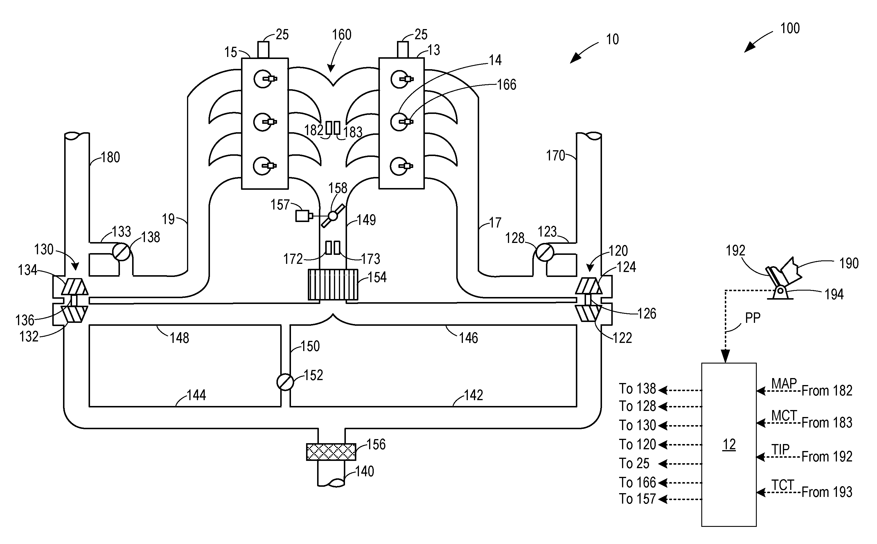
[0015]The following description relates to methods for controlling a turbocharged engine, such as depicted in FIGS. 1-2, by adjusting the turbocharger (for example, via a wastegate position, a variable vane position, a variable nozzle position, etc.), and throttle concurrently. Using combined feedback and feed-forward control mechanisms, a turbocharger can be controlled while regulating the throttle inlet pressure. By using non-linear models of the turbocharger dynamic system and the engine airflow system, as depicted in FIG. 3, the measured throttle inlet pressure signal may be combined with measured airflow signals, to separate effects on throttle inlet pressure due to control errors and other conditions (that are addressed by the wastegate solenoid duty cycle control) from disturbances due to throttle movement or changes in throttle flow due to other factors such as engine speed or cam timing changes. An engine controller may perform example control routines, such as those elabor...


PUM


Abstract

Methods are provided for controlling a turbocharged engine having a throttle and a turbocharger. One example method comprises, moving the throttle during boosted conditions, separating out effects on the throttle inlet pressure into a first portion corresponding to disturbances caused by the movement of the throttle, and a second, remaining, portion. The method further comprises adjusting the turbocharger based on the second portion and not the first portion.

Description

FIELD[0001]The present application relates to methods and systems for feedback and feed-forward control of an engine turbocharger.BACKGROUND AND SUMMARY[0002]Engines with turbochargers may use active control of the turbocharger, such as via a wastegate, intake throttle, a compressor bypass, etc., to improve engine performance and thus vehicle driveability.[0003]Various approaches are known for controlling such engine systems based on a desired throttle inlet pressure (TIP), where the throttle inlet pressure is downstream of the turbocharger compressor, and upstream of the throttle, in the engine air inlet. However, the inventors herein have recognized limitations with such approaches.[0004]One example approach requires that the throttle be fixed at wide open when performing boost control with the wastegate. As such, this approach eliminates the potential disturbances from the throttle, at the expense of performance and driveability improvements that can be gained by using the faster...

Claims


Application Information

Patent Timeline
Patent Type & Authority Applications(United States)
IPC IPC(8): F02D23/00
CPCF02B37/007F02B37/18F02B37/24F02D41/0007Y02T10/144F02D2041/141F02D2041/1416F02D2041/1433F02D2200/0404F02D41/1401Y02T10/12
Inventor DOERING, JEFFREY ALLENROLLINGER, JOHN ERICCHEN, DE-SHIOU
Owner FORD GLOBAL TECH LLC
Learn More