System for actively controlling compressor clearances

a compressor and clearance technology, applied in the field of turbine engines, can solve the problems of large clearances b>22/b>, extended outages, and substantial component damage, and achieve the effects of reducing the clearance of compressors

Inactive Publication Date: 2008-10-14
SIEMENS ENERGY INC
View PDF25 Cites 47 Cited by
  • Summary
  • Abstract
  • Description
  • Claims
  • Application Information

AI Technical Summary

Benefits of technology

[0011]The vane carrier can be at a first temperature, and the thermal fluid can be at a second temperature. In one embodiment, the second temperature can be greater than the first temperature. Thus, the temperature of the vane carrier can be raised above the first temperature after the thermal fluid is passed through the channel. Consequently, the compressor clearances can be enlarged or at least maintained during non-standard operating conditions. In another embodiment, the second temperature can be less than the first temperature. Thus, the temperature of the vane carrier can be lowered below the first temperature after the thermal fluid is passed through the channel. As a result, the compressor clearances can be reduced or at least maintained during operating conditions where improved engine performance is desired.
[0016]The fluid is passed in heat exchanging relation through the one or more channels so as to lower the temperature of the vane carrier below the first temperature. As a result, the vane carrier radially contracts or at least radial expansion of the vane carrier is minimized.

Problems solved by technology

Small clearances are desired to keep air leakage to a minimum; however, it is critical to maintain a clearance between the rotating and stationary components at all times. Rubbing of any of the rotating and stationary components can lead to substantial component damage, performance degradation, and extended outages.
However, because the minimum tip clearances 22 are sized for these off design conditions, the clearances 22 become overly large during normal engine operation, such as at base load.
In addition, the spallation of the coating 30 has resulted in large patches of uncoated surfaces.

Method used


Image

  • System for actively controlling compressor clearances
  • System for actively controlling compressor clearances
  • System for actively controlling compressor clearances

Examples


Embodiment Construction

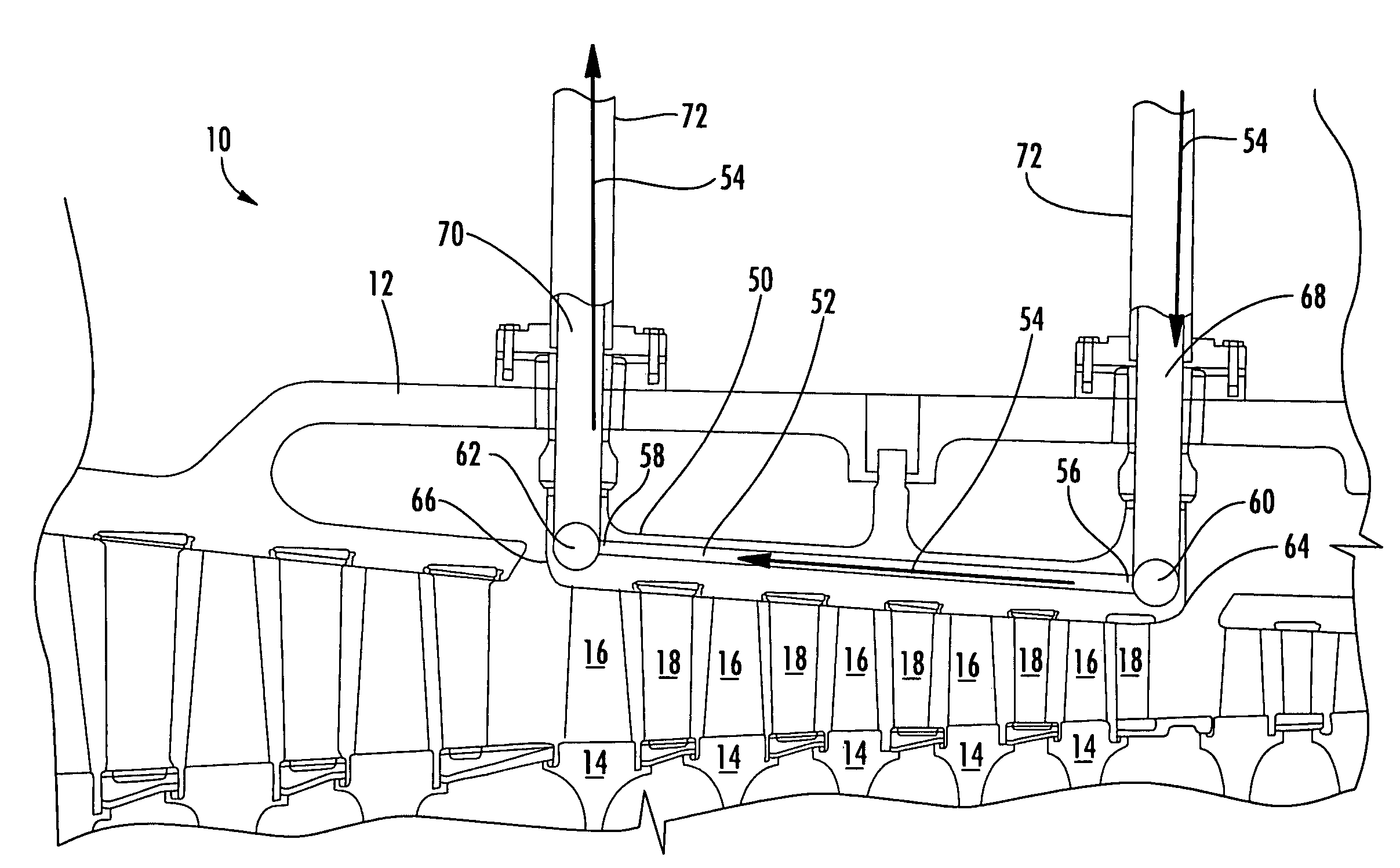
[0030]Embodiments of the present invention address the shortcomings of prior compressor clearance control systems by providing a vane carrier adapted to receive a thermal fluid for altering the temperature of the vane carrier. Embodiments of the invention will be explained in connection with various possible vane carrier heating and cooling systems and methods, but the detailed description is intended only as exemplary. Embodiments of the invention are shown in FIGS. 3-9, but the present invention is not limited to the illustrated structure or application.

[0031]A blade ring or vane carrier 50 configured according to aspects of the invention is shown in FIG. 3. The vane carrier 50 can be generally cylindrical in conformation. The vane carrier 50 can be a single piece, or the vane carrier 50 can be made of multiple pieces. For example, the vane carrier 50 can be made of two semi-cylindrical halves. It will be understood that aspects of the invention can be applied to any of vane carri...


PUM


Abstract

Aspects of the invention relate to a system and method for actively controlling compressor clearances in a turbine engine by passing a thermal fluid in heat exchanging relation through a compressor vane carrier. During some operational conditions, such as hot restart or spin cool, it may be desirable to heat the vane carrier to enlarge or at least prevent a decrease in compressor clearances. In such cases, a heated thermal fluid can be provided by reclaiming residual exhaust energy from a heat recovery steam generator. At any condition where improved performance is desired, such as at base load operation, the vane carrier can be cooled to minimize compressor clearances. A cooled thermal fluid can be bleed air from an upstream portion of the compressor, water-cooled high pressure bleed air from a downstream portion of the compressor, or feed water from the bottoming cycle in a combined cycle engine.

Description

FIELD OF THE INVENTION[0001]The invention relates in general to turbine engines and, more specifically, to compressor clearance control.BACKGROUND OF THE INVENTION[0002]As shown in FIG. 1, the compressor section 10 of a turbine engine is enclosed within an outer casing 12. The compressor can include a rotor (not shown) with a plurality of axially spaced discs 14. Each disc 14 can host a row of rotating airfoils, commonly referred to as blades 16. The rows of blades 16 alternate with rows of stationary airfoils or vanes 18. The vanes 18 can be provided as individual vanes, or they can be provided in groups such as in the form of a diaphragm. The vanes 18 can be mounted in the compressor section 10 in various ways. For example, one or more rows of vanes 18 can be attached to and extend radially inward from the compressor shell 12. In addition, one or more rows of vanes 18 can be hosted by a blade ring or vane carrier 20 and extend radially inward therefrom.[0003]The compressor section...

Claims


Application Information

Patent Timeline
Patent Type & Authority Patents(United States)
IPC IPC(8): F02C6/08F02C6/18F02C7/12F02C7/16
CPCF01D11/24F01D25/08F01D25/14F02C6/08F02C7/12F02C7/185F05D2270/305F05D2260/20F05D2260/205
Inventor PAPROTNA, HUBERT EDWARDFOUST, ADAM MATTHEW
Owner SIEMENS ENERGY INC
Why Eureka
Try Eureka