Inverter trasformer

a technology of inverter transformer and transformer body, which is applied in the direction of transformer/inductance details, basic electric elements, and inductance, etc., can solve the problems of reducing the amount of leakage flux spreading around the inverter transformer, affecting the arrangement and reducing the influence of components and wires. , the effect of preventing cost increas

Inactive Publication Date: 2006-06-22
MINEBEA CO LTD
View PDF5 Cites 14 Cited by
  • Summary
  • Abstract
  • Description
  • Claims
  • Application Information

AI Technical Summary

Benefits of technology

[0023] Since the magnetic resin formed of a resin containing a magnetic substance is disposed so as to cover at least one portion of the winding unit so that the primary and the secondary windings have respective predetermined leakage inductances, the amount of leakage flux spreading around the inverter transformer is reduced compared with when the winding unit is not covered by the magnetic resin, which results in having a reduced influence on the components and wires arranged around the inverter transformer. This structure also contributes to making it harder for the characteristics of the inverter transformer to suffer the effects of metals present around the inverter transformer. When the winding unit is totally covered by the magnetic resin, a case for shielding is not required, which prevents cost increase, and which eliminates the need of fixing the inverter transformer inside the case and taking out lead wires from the case thus easing the manufacturing process. This total coverage by the magnetic resin increases mechanical strength of the inverter transformer thus enhancing product reliability.
[0024] Also, the number of turns and the leakage inductance on the winding can be adjusted to the optimum conditions of the circuit operation by adjusting the magnetic characteristics such as relative magnetic permeability of the magnetic resin and adjusting the coverage area and thickness of the magnetic resin. Consequently, the inductance value can be adjusted without changing the number of turns on the primary and secondary windings and the configuration and characteristics of the bar-shaped magnetic core, thus providing applicability to various inverter transformers.
[0025] And, since the external unit having a larger saturation magnetic flux density than the magnetic resin is disposed so as to cover at least one portion of the circumference of the transformer body including the at least one winding unit and the magnetic resin, most of the magnetic flux leaking out from the bar-shaped magnetic core so as to pass through the magnetic resin and then to leak out further from the magnetic resin is adapted to pass through the external unit. Consequently, the amount of the leakage flux can be reduced effectively compared when the magnetic flux is prevented from leaking out by the magnetic resin only without providing the external unit, and therefore the thickness of the magnetic resin can be reduced, which results in reduction of the entire cross section area of the inverter transformer thus downsizing the inverter transformer.

Problems solved by technology

Further, even after discharging a CCFL, the voltage at the time of starting discharge must be maintained, which is disadvantageous in view of safety.
However, magnetic flux leaks from the bar-shaped magnetic core, especially from the ends thereof
In an inverter transformer involving leakage inductance, leakage flux may possibly influence neighboring components or wires, or emit noises, and the components and wires must be appropriately located in order to keep away from the leakage flux thus placing restrictions on arrangement of components and wires.
This may result in increase of product dimension or deterioration of characteristics.
Also, if a magnetic material is placed at the path of the leakage flux, the flux path may be influenced when the leakage flux passes through the magnetic material, which causes the leakage inductance to vary or fluctuate disturbing stability, further causing the inverter transformer to undergo variation in characteristic and consequently to undergo change in operation.
Thus, an inverter transformer including only a bar-shaped magnetic core is simple in structure but suffers increase in leakage flux distribution range, and also has difficulty in adjusting the amount of leakage inductance.
Also, when engaging the bar-shaped magnetic core with the rectangular frame-shaped magnetic core, a complex and troublesome process of putting gap sheets therebetween is required for adjusting leakage inductance.
This solution by magnetically shielding a product, however, requires a shielding case, and this leads to increase in product dimension and product cost.
Also, processes of fixing the inverter transformer to the shielding case and taking out lead wires from the shielding case are additionally required, thus making cost reduction further difficult.
And, a defective fixing of the inverter transformer to the shielding case may raise deterioration in reliability.
On the other hand, an inverter transformer employing a rectangular frame-shaped magnetic core together with a rectangular frame-shaped magnetic core, while generating a reduced amount of leakage flux, has a complicated structure and requires additional troublesome manufacturing processes thus pushing up production cost.

Method used


Image

  • Inverter trasformer
  • Inverter trasformer
  • Inverter trasformer

Examples


example

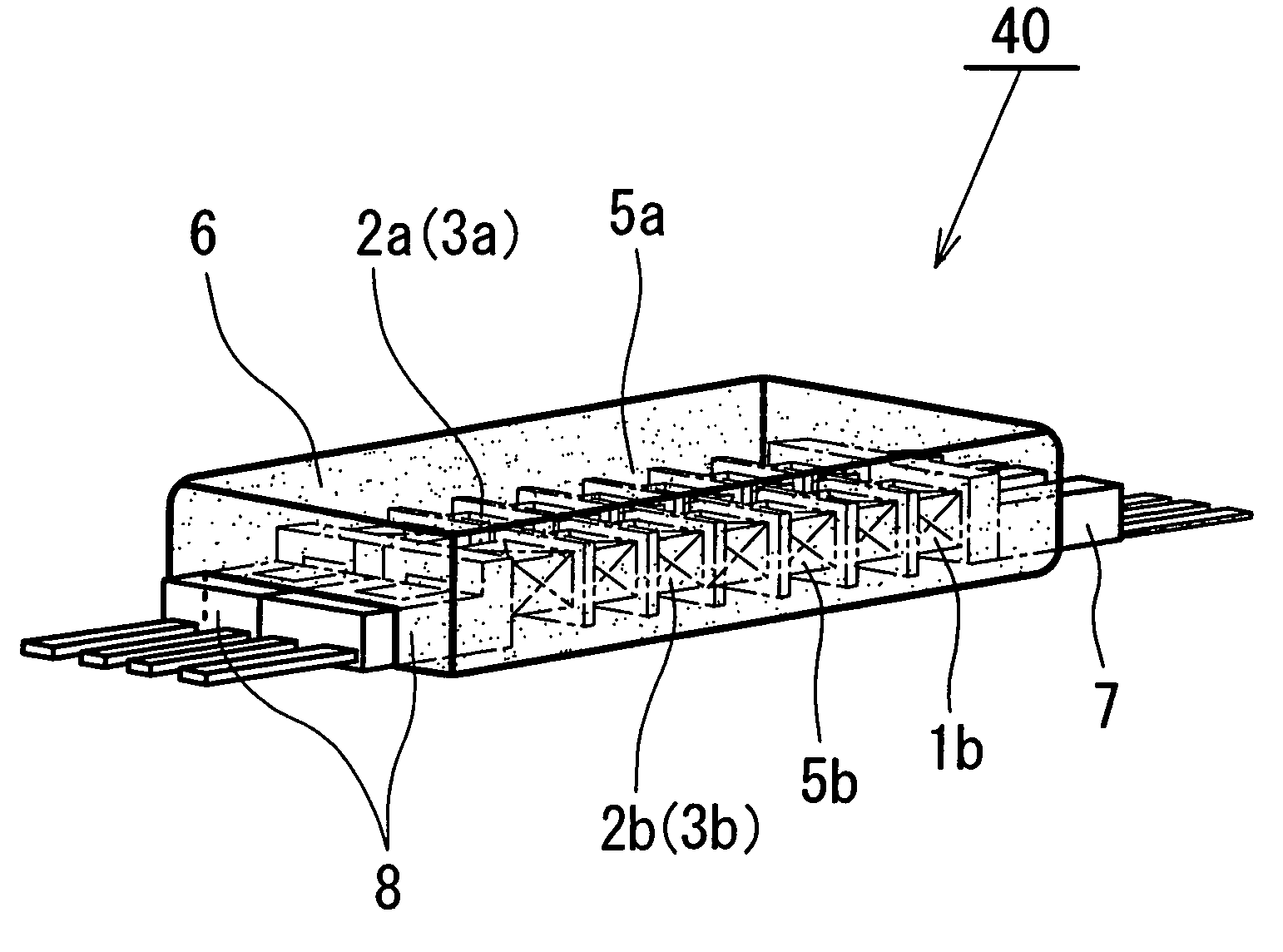
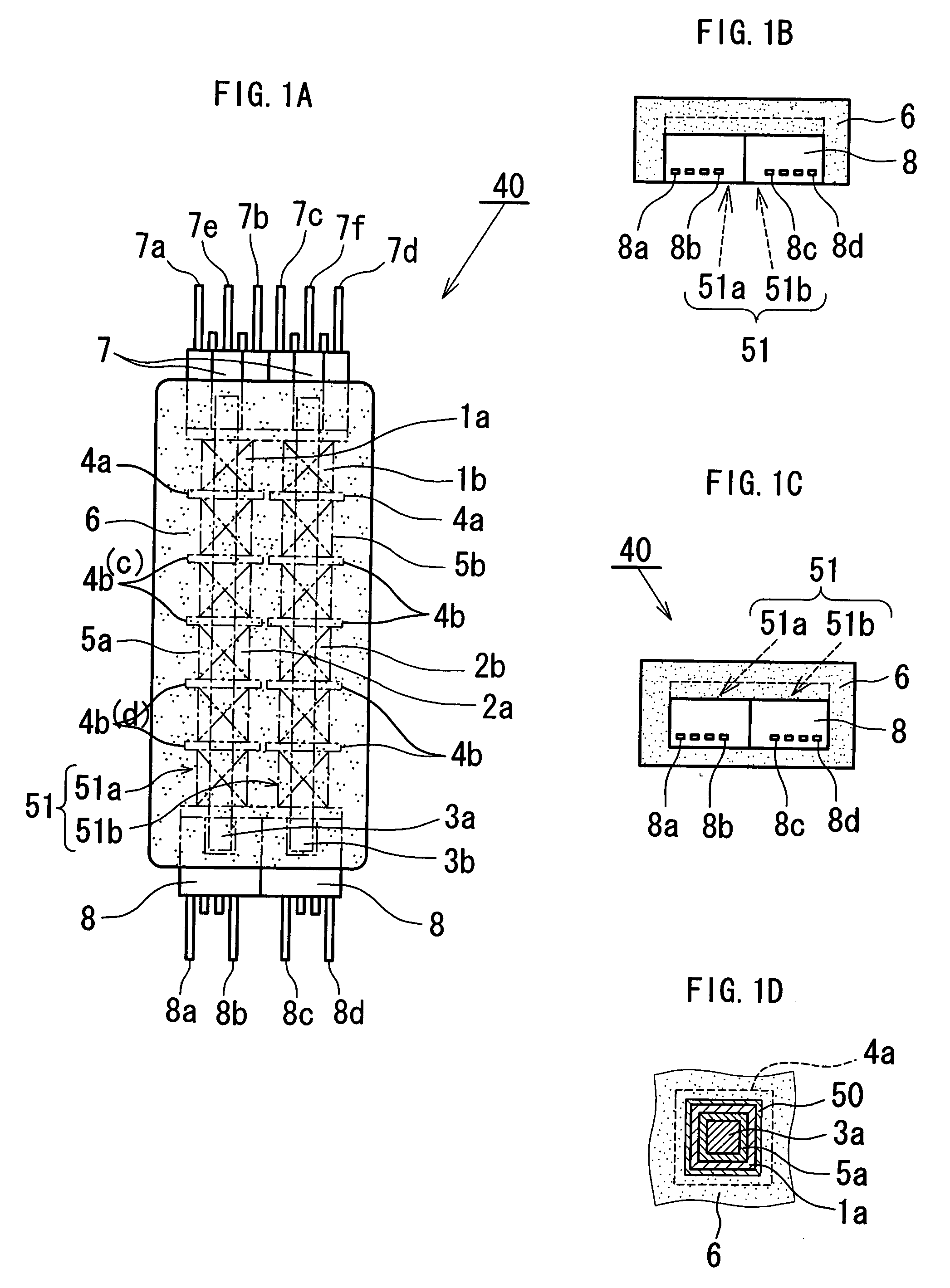
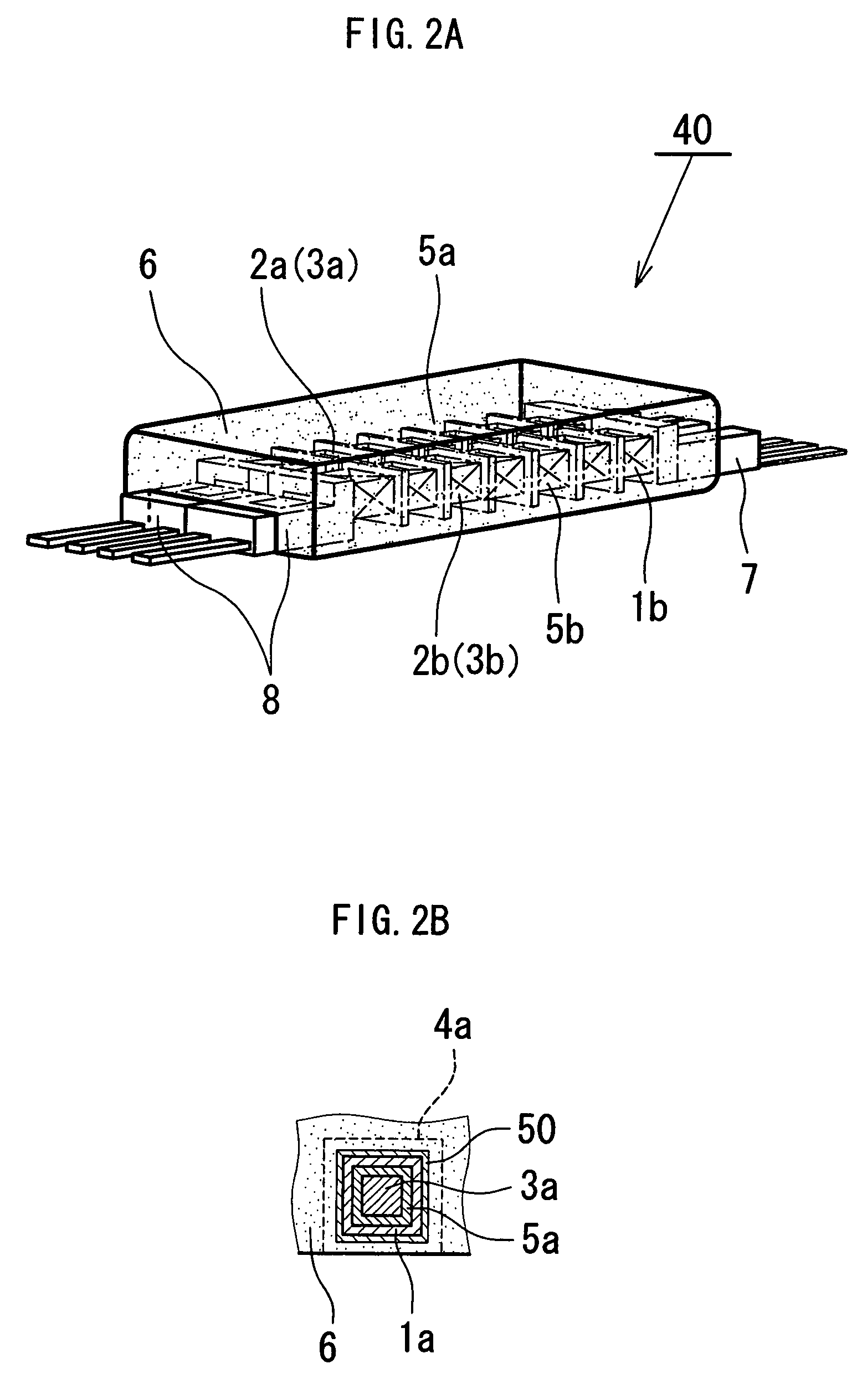
[0094] The inverter transformer 40 according to the second embodiment described above will hereinafter be explained as an example. In the inverter transformer 40 as an example: the cores 3a and 3b are formed of Mn—Zn ferrite having a relative magnetic permeability of 2000 and have a height of 3 mm, a width of 3 mm, and a length of 30 mm; the magnetic resin 6 is made such that Mn—Zn ferrite powder having a relative magnetic permeability of about 2000 is mixed with a thermosetting epoxy resin in a volume ratio of 80%; the terminal blocks 7 and 8 are formed of an insulating material and have a height of 6 mm; the bobbins 5a and 5b have a height of 3 mm; the insulating partitions 4b between each section have a height of 2 mm; and the primary windings 1a and 1b and the secondary windings 2a and 2b are wound around the bobbins 5a and 5b and have a winding thickness of about 0.5 mm.

[0095] In the example of the inverter transformer 40 as described above, the magnetic resin 6 was arranged a...


PUM

PropertyMeasurementUnit
frequencyaaaaaaaaaa
lengthaaaaaaaaaa
voltageaaaaaaaaaa

Abstract

In an inverter transformer, a primary winding and a secondary winding are wound around each of two bar-shaped magnetic cores, and a magnetic resin covers all or some portions, including at least both end portion of the circumference, of the bar-shaped magnetic cores so that the primary and the secondary windings have respective predetermined leakage inductances. The magnetic resin has a substantially smaller relative magnetic permeability than the bar-shaped magnetic cores. Part of magnetic flux generated at the bar-shaped magnetic cores leaks out beyond the bar-shaped magnetic cores and further beyond the magnetic resin so as to provide leakage inductance, which functions as ballast inductance. Also, the amount of magnetic flux passing through the magnetic resin and leaking out beyond the magnetic resin is reduced, and influence to the area around the inverter transformer is reduced.

Description

BACKGROUND OF THE INVENTION [0001] 1. Field of the Invention [0002] The present invention relates to an inverter transformer for use in an inverter circuit to light a discharge lamp, such as a cold cathode fluorescent lamp, as a light source of a lighting device for a liquid crystal display. [0003] 2. Description of the Related Art [0004] Currently, a liquid crystal display (LCD) is increasingly used as a display unit for a personal computer, and the like. The LCD lacks a light emitting function, and therefore requires a lighting device, such as a back-light system or a front-light system, and a cold cathode fluorescent lamp (CCFL) is generally used as a light source for such a lighting device. In case of discharging and lighting a CCFL having a length, for example, about 500 mm, an inverter circuit is used which is adapted to generate a high-frequency voltage of 60 kHz, about 1600 V at the time of starting discharge. The inverter circuit controls a voltage applied to the CCFL such ...

Claims


Application Information

Patent Timeline
Patent Type & Authority Applications(United States)
IPC IPC(8): H01F5/00H01F3/10H01F27/02H01F38/08H01F38/10
CPCH01F3/10H01F27/022H01F38/08H01F38/10H01F2017/048H01F27/02
Inventor SHINMEN, HIROSHINORIZUKI, MASASHI
Owner MINEBEA CO LTD
Why Eureka
Try Eureka