
Junction box for solar cell module

A technology of solar cell components and junction boxes, applied in the field of photovoltaics, can solve problems such as limited cooling effect, drop, poor thermal conductivity, etc., achieve the effects of improving stability and installation efficiency, reducing the probability of damage, and saving cable connections

Active Publication Date: 2011-05-04
WUXI SUNTECH POWER CO LTD
View PDF2 Cites 3 Cited by
  • Summary
  • Abstract
  • Description
  • Claims
  • Application Information

AI Technical Summary

Problems solved by technology

The disadvantage of such a junction box is: since the components all use a junction box, more cables are needed when the components are connected in series, and because the box body of the junction box is separated from the connector of the cable, it is necessary to install the system when installing the system. Fix the cables connected between the junction boxes to prevent the connection effect from being unstable due to the weight of the cables themselves and the connectors, which will reduce the efficiency of system installation; in addition, the bypass diode is enclosed in the junction box, and due to the wiring The inside of the box is in direct contact with the conductive sheet or terminal block installed with the bypass diode is a medium with poor thermal conductivity, so the heat generated when the bypass diode is working is difficult to dissipate, which will cause the temperature of the bypass diode to be too high and shorten The service life of the bypass diode, and even make the bypass diode invalid, and then make the assembly burn or the quality declines. In order to solve this problem, in the junction box of the prior art, some have a heat dissipation structure inside the junction box, but this will Increasing the size of the junction box or the size of the heat dissipation structure is limited by the space inside the junction box, so the heat cannot be quickly and effectively transferred to the outside of the junction box, so the heat dissipation effect is limited, and long-term use will also cause heat accumulation.
But in this new type of module, since each junction box contains only one diode in parallel with the branch circuit, when there are more branches in the module, multiple junction boxes are required, which will also increase the cost of the module

Method used


Image

  • Junction box for solar cell module
  • Junction box for solar cell module
  • Junction box for solar cell module

Examples


Embodiment Construction

[0027] The following will clearly and completely describe the technical solutions in the embodiments of the present invention with reference to the accompanying drawings in the embodiments of the present invention. Obviously, the described embodiments are only some, not all, embodiments of the present invention. Based on the embodiments of the present invention, all other embodiments obtained by persons of ordinary skill in the art without making creative efforts belong to the protection scope of the present invention.

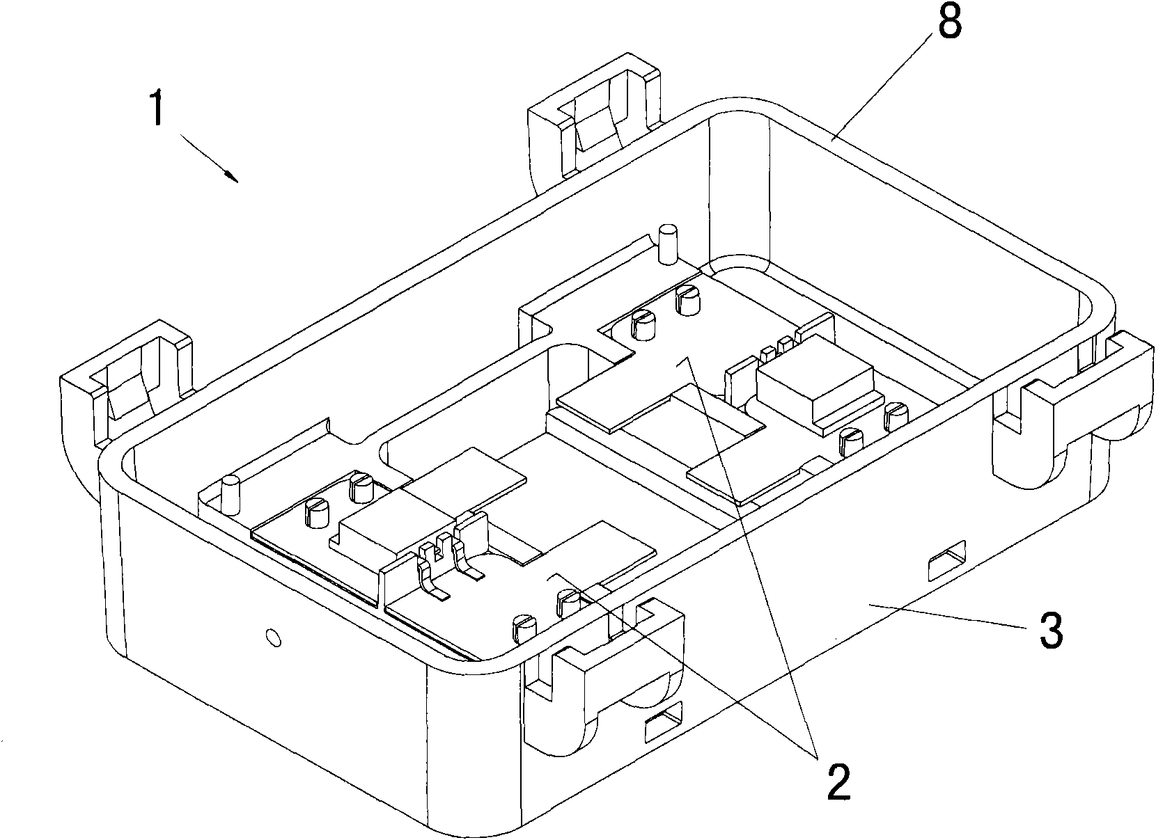
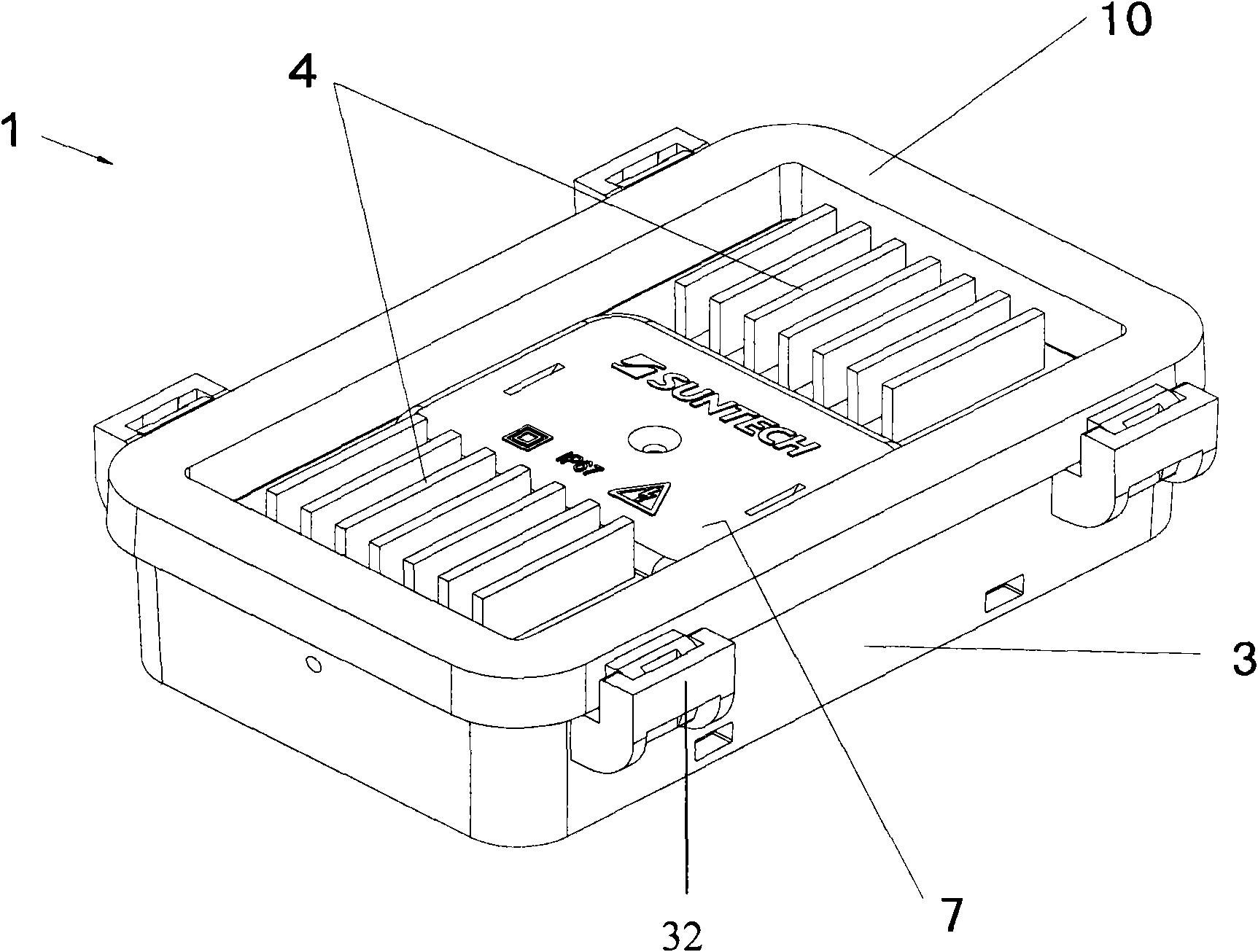
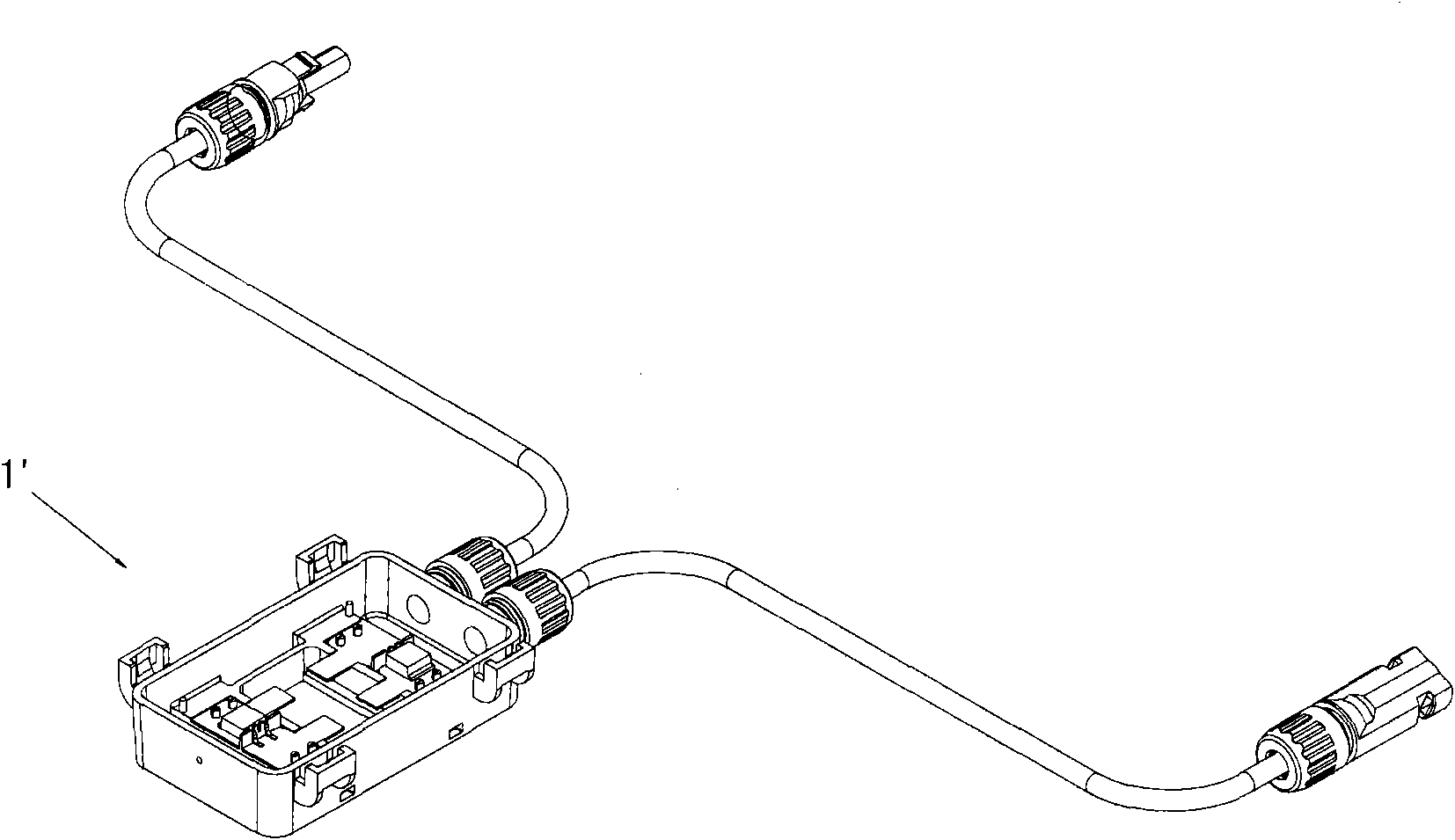
[0028] figure 1 It is a schematic diagram of an embodiment of the junction box for solar cell modules of the present invention, figure 2 for figure 1 The schematic diagram of the junction box shown for the solar cell module is installed on the box cover. like figure 1 and figure 2 As shown, the solar cell module junction box 1 of this embodiment includes a box cover 10, a box body 3 and at least two control circuits 2 arranged in the box body 3, and ther...


PUM


Abstract

The invention discloses a junction box for a solar cell module. The junction box comprises a box cover, a box body and at least two control circuits which are arranged in the box body and are not directly and electrically connected mutually, wherein each control circuit comprises a diode; each control circuit is connected in parallel with a branch circuit which is formed by connecting in series at least one solar cell unit in the solar cell module; the box cover is provided with a heat radiating component; the box body is provided with a cable connecting piece; the diode is connected with theheat radiating component through a connecting component; and the connecting component is made of a material with high insulating heat conductivity. In the junction box, cable connecting wires among junction boxes can be saved, the installation efficiency of systems is improved, heat radiating effect is good; moreover, the number of the junction boxes used in multiple-branch solar cell modules canbe reduced.

Description

technical field [0001] The invention relates to the field of photovoltaics, in particular to a junction box for a solar battery module. Background technique [0002] In recent years, in the development of alternative energy sources, solar cell technology has made great breakthroughs, and its applications have become more and more extensive. A solar cell module is generally composed of 54 to 72 solar cells connected in series. Inside the solar cell module, in order to protect the solar cell from being burned out when the hot spot effect occurs, usually each solar cell module consists of 18-24 solar cells. The branches connected in series of solar cells are connected in parallel with a bypass diode. Multiple bypass diodes are arranged in a component junction box and installed on the conductive sheet or junction seat inside the box body. The junction box has lead-out cables, and then each wiring The boxes are connected to each other by cables and connectors so as to realize th...

Claims


Application Information

Patent Timeline
IPC IPC(8): H02N6/00H02G3/08
CPCH02S40/34H02S40/345Y02E10/50
Inventor 聂俊波陈志良蔡世俊
Owner WUXI SUNTECH POWER CO LTD
Learn More