
Flat-needle electric stapler

A stapler and flat needle technology, applied in the direction of manufacturing tools, staple staple tools, etc., can solve the problems of being fixed in one position, poor binding effect, and limited application scope.

Pending Publication Date: 2022-07-22
宁波伟书电子科技有限公司
View PDF1 Cites 0 Cited by
  • Summary
  • Abstract
  • Description
  • Claims
  • Application Information

AI Technical Summary

Problems solved by technology

[0004] Although the existing flat needle stapler solves the problem of the height of the stitches, but because the paper is placed on the movable plate for binding, the upper needle box assembly and the lower The movable plate will move, causing the paper to be unstable during the binding process. It is difficult to fix the paper and keep the paper in one position, which will lead to the phenomenon of staple binding offset. The binding effect is poor and may not meet the user's expected binding. Effect
At the same time, due to the structural limitation of the functional area of ​​the pin groove sheet, the binding capacity of the existing 1 / 4 inch (or 24 / 6 & 26 / 6) staples is difficult to break through the technical problem of binding the maximum number of papers with a thickness of 3mm. limit its scope of application

Method used


Image

  • Flat-needle electric stapler
  • Flat-needle electric stapler
  • Flat-needle electric stapler

Examples


Embodiment Construction

[0056] The present invention will be further described below with reference to the specific embodiments. It should be noted that, on the premise of no conflict, the embodiments or technical features described below can be arbitrarily combined to form new embodiments.

[0057] In the description of the present invention, it should be noted that for orientation words, such as the terms "center", "horizontal", "longitudinal", "length", "width", "thickness", "upper", "lower" , "Front", "Back", "Left", "Right", "Vertical", "Horizontal", "Top", "Bottom", "Inside", "Outside", "Clockwise", "Counterclockwise" ” and the like indicating the orientation and positional relationship are based on the orientation or positional relationship shown in the accompanying drawings, which are only for the convenience of describing the present invention and simplifying the description, rather than indicating or implying that the referred device or element must have a specific orientation or a specific ...


PUM


Abstract

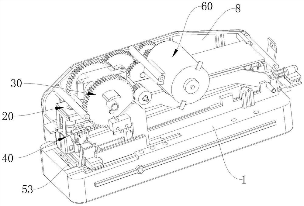
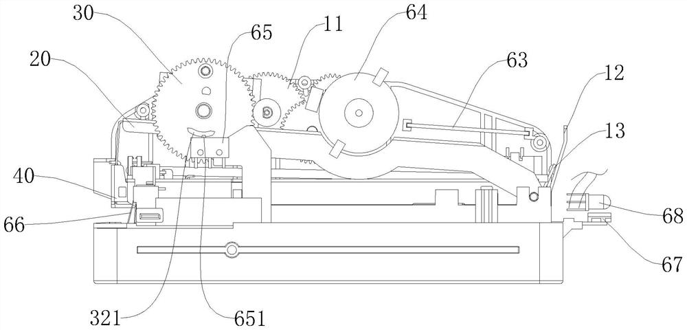
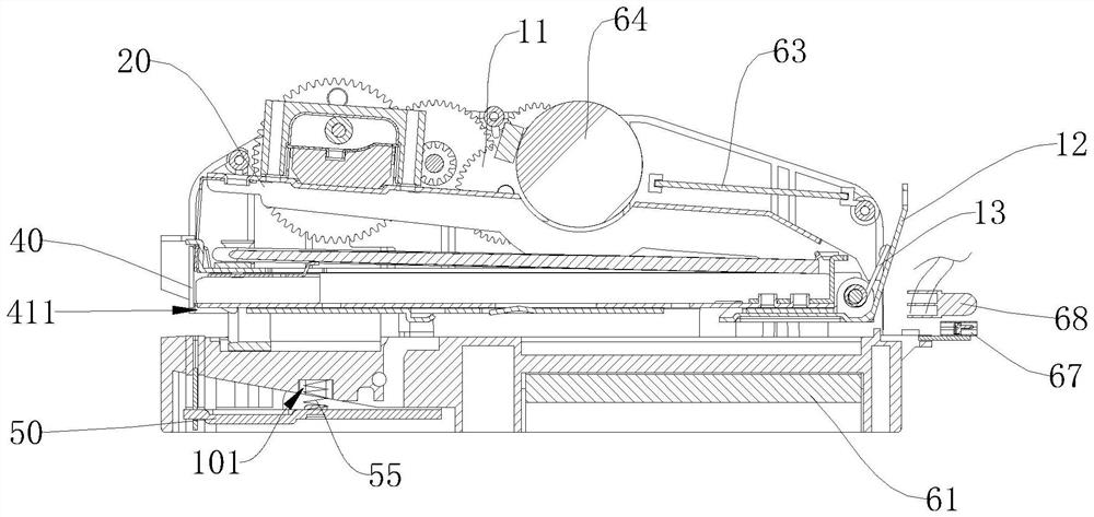
The invention discloses a flat-needle electric stapler which comprises a base, a transmission mechanism and a driving assembly, the driving assembly is used for driving the transmission mechanism, the transmission mechanism comprises a needle pressing mechanism assembly and a flat-needle mechanism assembly, the needle pressing mechanism assembly is pivoted to the upper portion of the base, the needle pressing mechanism assembly is provided with a needle outlet, and the flat-needle mechanism assembly is arranged on the base. The staple pressing mechanism assembly is used for pressing out staples at the staple outlet, the staple flattening mechanism assembly comprises a staple groove piece and a flattening piece, the staple groove piece is fixed to the front end of the base and provided with a staple groove and a guide groove located below the staple groove, the guide groove is formed in the staple groove piece, and the staple groove is located below the staple outlet. The stitch of the staple is bent on the two side walls of the staple groove, and the flattening piece is arranged in the guide groove in a sliding mode and used for flattening the stitch of the staple upwards. Therefore, stitches of staples are effectively and automatically flattened through the needle flattening mechanism assembly, the binding position of a binding object is basically kept, and unstable movement of the binding object is prevented.

Description

technical field [0001] The invention relates to the technical field of staplers, in particular to a flat needle electric stapler. Background technique [0002] As a binding tool, staplers are widely used in home and office environments. The working principle of the existing ordinary stapler is: when the end cover of the stapler is pressed hard, the top piece, the needle and the clamp will rotate around the connecting pin; with the continuous application of the force, the top piece will rotate away from its natural state At this time, the top will move up and down around the connecting pin, which is slightly larger than a needle height, the end cap spring is compressed, and the shrapnel is compressed, which will drive the needle to move downward. After moving a certain distance, the needle will touch the working plane. The paper is passed through the paper under the action of manpower and then encounters the die, and the needle is bent, so as to achieve penetration binding b...

Claims


Application Information

Patent Timeline
Patent Type & Authority Applications(China)
IPC IPC(8): B25C5/02B25C5/15
CPCB25C5/15B25C5/02B25C7/00
Inventor 代长海
Owner 宁波伟书电子科技有限公司
Learn More