Labor-saving stapler

A technology of a stapler and a knife holder, applied in the field of machinery, can solve the problems of poor labor-saving effect and no change, and achieve the effects of simple structure, high practical value, and obvious labor-saving effect.

Active Publication Date: 2013-11-27
SUNWOOD HLDG GROUP
View PDF6 Cites 10 Cited by
  • Summary
  • Abstract
  • Description
  • Claims
  • Application Information

AI Technical Summary

Problems solved by technology

It uses the principle of leverage to achieve a certain labor-saving effect during use, but the labor-saving effect is poor during use, especially when the upper cover is pressed down, the lengths of the resistance arm and the power arm do not change. Always requires the user to maintain a large force to complete the binding

Method used


Image

  • Labor-saving stapler
  • Labor-saving stapler
  • Labor-saving stapler

Examples


Embodiment 1

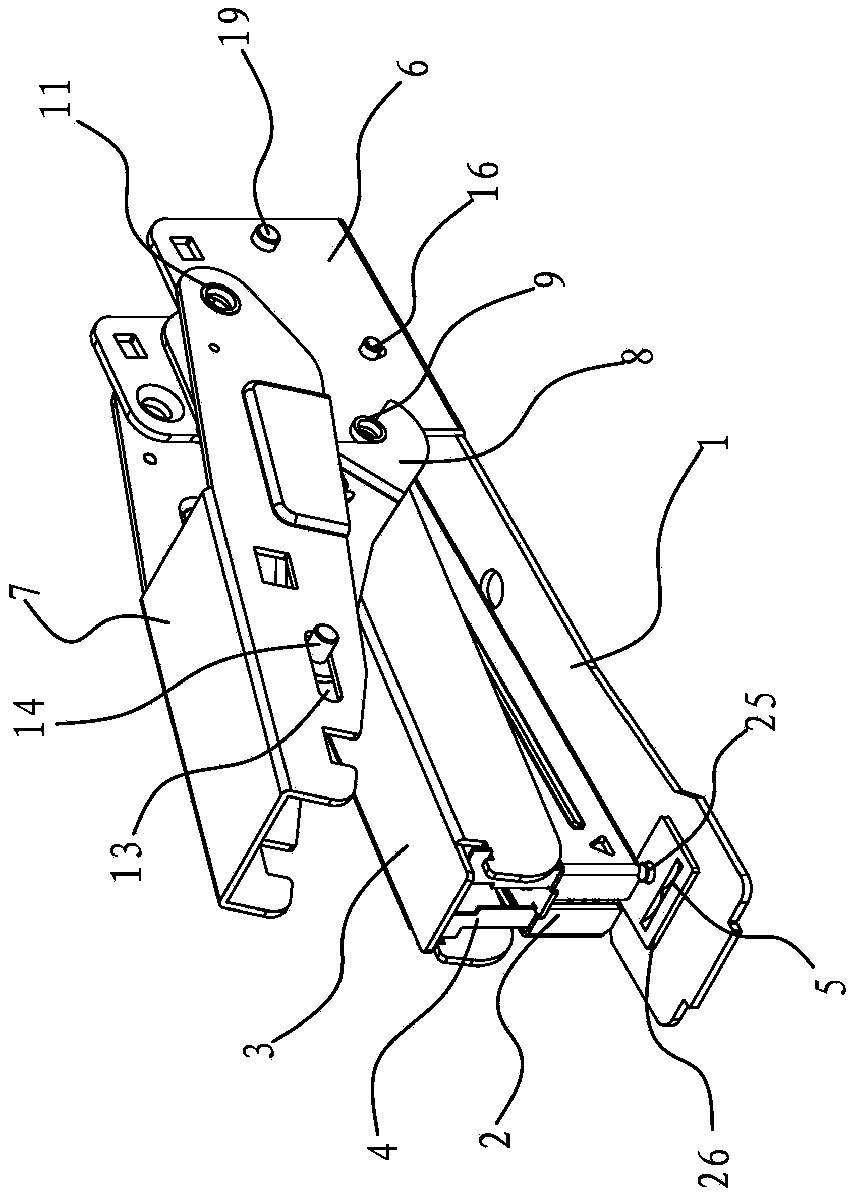
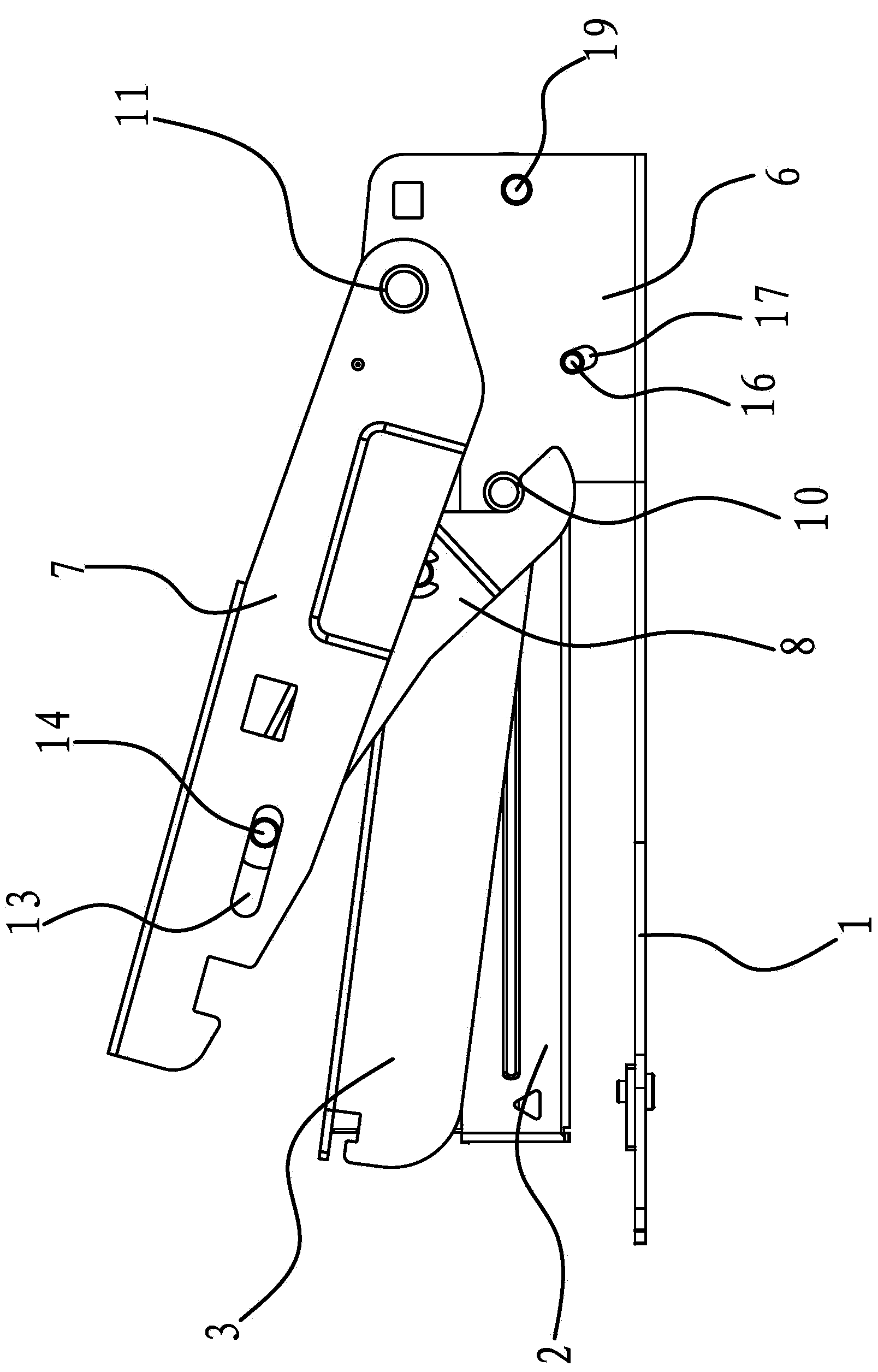
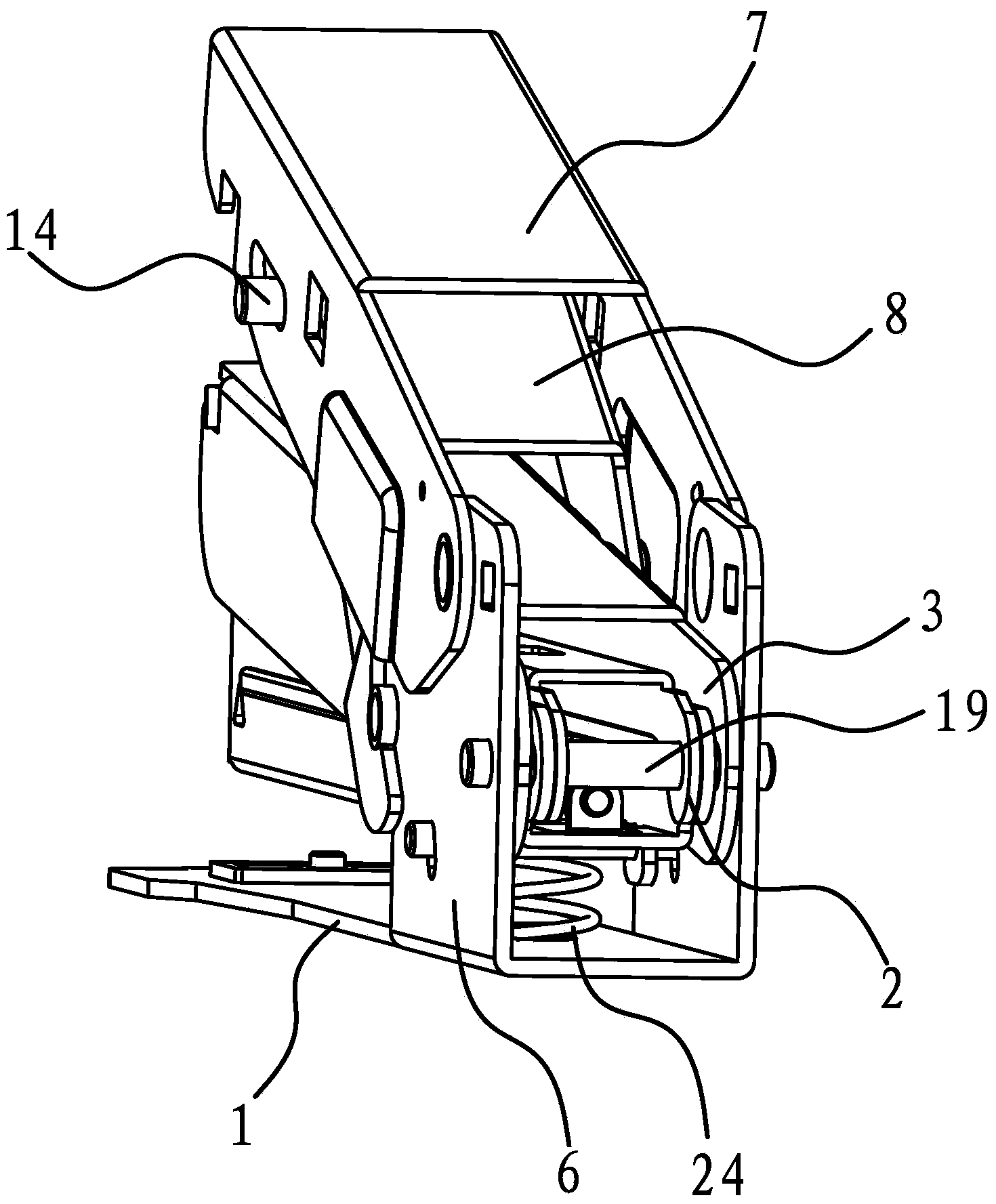
[0031] Such as Figure 1-Figure 4 As shown, a labor-saving stapler comprises a base 1, a nail path 2 and a knife rest 3, the outer end of the knife rest 3 is provided with a blade 4, and the outer end of the base 1 is fixedly connected with a connecting plate 26 by a screw 25, and on the connecting plate 26 Be provided with knife edge 5. The inner end of the base 1 has a positioning bracket 6, the two sides of the positioning bracket 6 have connecting holes 18 and a connecting shaft 19 is arranged between the two connecting holes 18, and the connecting shaft 19 passes through the inner end of the tool holder 3 and the inner end of the nail path 2 respectively. . In this embodiment, a return spring 24 is provided between the base 1 and the bottom of the nail track 2 , and the nail track 2 tends to move upward under the elastic force of the return spring 24 . There are protruding connecting parts 15 on both sides of the bottom of the inner end of the nail channel 2, and a limi...

Embodiment 2

[0041] The structure and principle of this embodiment are basically the same as that of Embodiment 1, the difference is that both sides of the outer end of the connecting frame 8 in this embodiment have guide grooves 13, and the two guide grooves 13 are oppositely arranged, and the iron cover 7 A guide pin 14 is transversely pierced between the two sides of the connecting frame 8 and the guide pin 14 passes through the guide grooves 13 on both sides of the outer end of the connecting frame 8 .


PUM


Abstract

The invention provides a labor-saving stapler which belongs to the technical field of machinery and solves the problem that an existing labor-saving stapler is poor in labor-saving effect in a use process. The labor-saving stapler comprises a base, a nail channel and a knife rest, wherein a blade is arranged on the outer end of the knife rest; a knife edge is arranged on the outer end of the base; a positioning bracket is arranged on the inner end of the base; the inner end of the nail channel and the inner end of the knife rest are hinged with the inner side of the positioning bracket; an iron cover is arranged above the knife rest; the inner end of the iron cover is hinged with the side part of the positioning bracket; a connection frame is arranged between the iron cover and the knife rest; the middle part of the connection frame is hinged with the middle part of the knife rest; the inner end of the connection frame is hinged with the side part of the positioning bracket; the outer end of the connection frame is connected with the inner side of the iron cover; a guide groove for enabling the outer end of the connection frame to slide back and forth along the inner side of the iron cover is arranged between the outer end of the connection frame and the inner side of the iron cover. The labor-saving stapler provided by the invention is simple in structure and good in labor-saving effect.

Description

technical field [0001] The invention belongs to the technical field of machinery and relates to a stapler, in particular to a labor-saving stapler. Background technique [0002] Stapler is an indispensable tool when people are studying and working, especially when they are working, documents are generally single sheets of paper, which are easy to scatter, so they need to be bound with a stapler. Ordinary staplers are push-type, and their structure usually includes a base, a binding box hinged on the base, and a gland. The staple pressing sheet on the pressing plate presses down the staples in the staple box and penetrates the paper, and then folds the staples inwards or outwards through the folding foot plate. [0003] In order to carry and use conveniently, the design length of the general stapler is not long, so it is necessary to apply greater pressure when using it, especially when binding more paper or thicker paper, it takes a lot of effort to finish it. Complete, so...

Claims


Application Information

Patent Timeline
Patent Type & Authority Applications(China)
IPC IPC(8): B25C5/02B25C5/11B25C7/00
Inventor 林夏森
Owner SUNWOOD HLDG GROUP
Why Eureka
Try Eureka