Method of enhancing clear field phase shift masks with border regions around phase 0 and phase 180 regions

A boundary region and phase region technology, applied in the field of patterning, can solve problems such as complex patterning of binary masks and limited manufacturing boundaries

Inactive Publication Date: 2006-11-15
GLOBALFOUNDRIES INC
View PDF4 Cites 0 Cited by
  • Summary
  • Abstract
  • Description
  • Claims
  • Application Information

AI Technical Summary

Problems solved by technology

Therefore, the patterning of binary masks can be complex and the manufacturing boundaries of this technology will be limited

Method used


Image

  • Method of enhancing clear field phase shift masks with border regions around phase 0 and phase 180 regions
  • Method of enhancing clear field phase shift masks with border regions around phase 0 and phase 180 regions
  • Method of enhancing clear field phase shift masks with border regions around phase 0 and phase 180 regions

Examples


Embodiment Construction

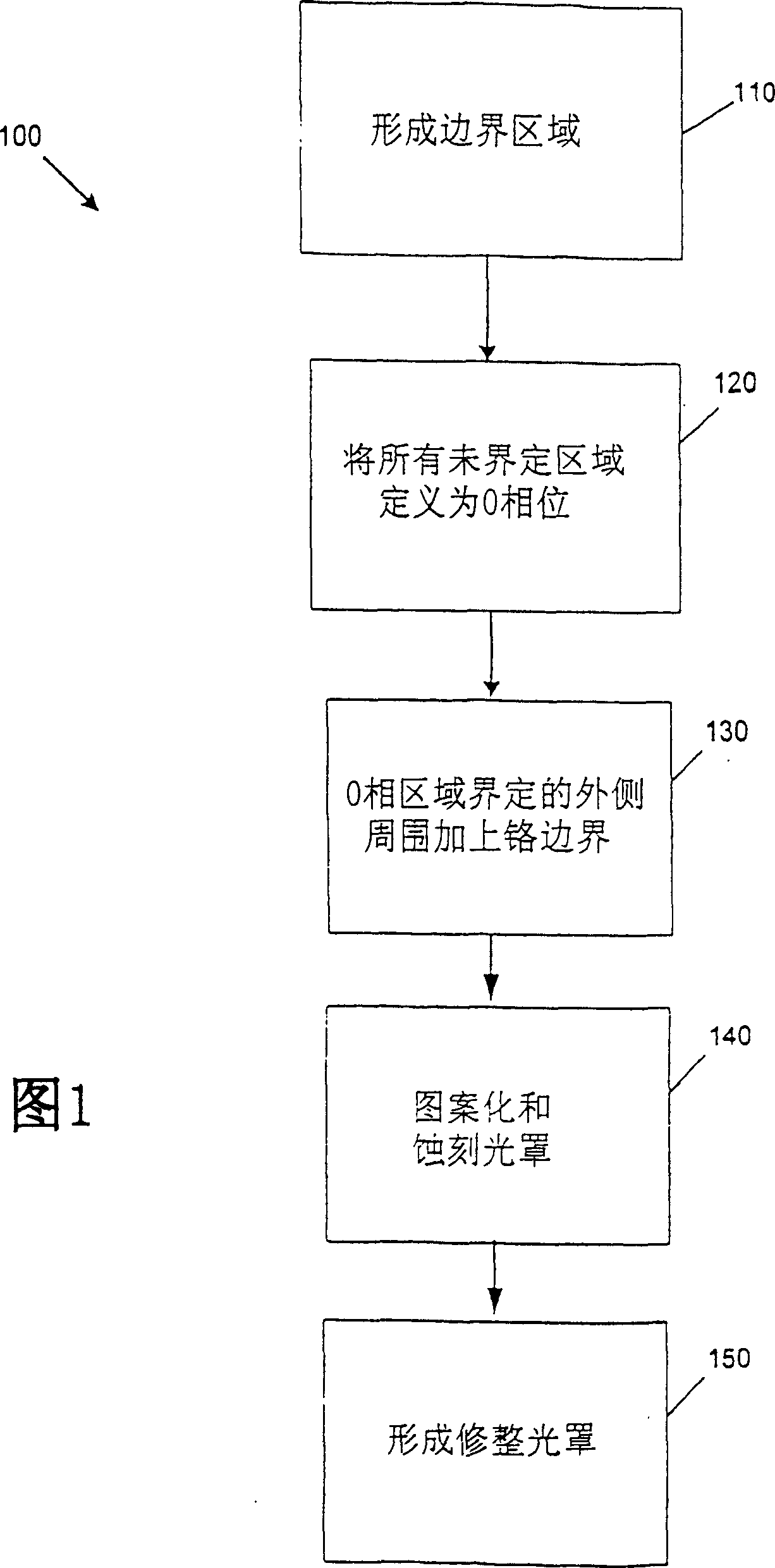
[0029] FIG. 1 shows a flowchart 100 describing example steps for forming or designing a phase shift mask (PSM) and a field or trim mask. A set of previously defined 0-phase regions or 180-phase regions on the phase mask can help identify critical polysilicon regions. These 0-phase regions or 180-phase regions can be created by hand, by using existing software programs, or by creating an optimal program to define these regions.

[0030] At step 110 , a chromium border region is formed on the phase mask outside of the 180 phase region edge of the previously defined 180 phase region that does not define the final polysilicon pattern. The chromium border area can be defined by hand drawing or by using a computer software program. The chromium border region has the advantage of allowing easy inspection of the mask and patterning the phase etching step of making the mask. At step 120, all undefined regions (final polysilicon pattern, or 180 phase regions, or chromium border region...


PUM


Abstract

The present invention discloses a technique of adding a first border area to each end of a 0-phase pattern defined as a polygon, and adding a second border area to each end of a 180-phase pattern. This technique can improve end-of-line pattern definition and improve manufacturability and patterning process margin. This increased border area balances the light on both sides of the line ends resulting in a more predictable final photoresist pattern.

Description

technical field [0001] The present invention generally relates to integrated circuits and methods of manufacturing integrated circuits. More particularly, the present invention relates to generating phase-shifting patterns to improve patterning of gates and other layers, structures, or regions requiring sub-nominal dimensions. Background technique [0002] A semiconductor device or integrated circuit (IC) may include millions of components such as transistors. Ultra Large Scale Integration (ULSI) may include Complementary Metal Oxide Semiconductor (CMOS) Field Effect Transistors (FETs). Although existing systems and processes are capable of manufacturing millions of IC components on an IC, there is still a need to reduce the size of the fine structure of the IC components to increase the number of components on the IC. [0003] One limitation in achieving the microstructure of smaller-sized IC components is the capability of existing photolithographic techniques. Photolit...

Claims


Application Information

Patent Timeline
Patent Type & Authority Patents(China)
IPC IPC(8): G03F1/00G03F9/00G03F1/34G03F1/26G03F1/30G03F1/36
CPCG03F1/30G03F1/36G03F1/70G03F1/34G03F1/26
Inventor T·P·卢康科C·A·斯彭斯
Owner GLOBALFOUNDRIES INC
Why Eureka
Try Eureka