Storage case

A storage box and main body technology, applied in the field of storage boxes, can solve the problems that the storage box 101 is easy to be dumped and the space is limited.

Inactive Publication Date: 2002-03-20
SONY CORP
View PDF0 Cites 15 Cited by
  • Summary
  • Abstract
  • Description
  • Claims
  • Application Information

AI Technical Summary

Problems solved by technology

This makes the storage box 101 in an unstable state causing the storage box 101 to fall easily
Moreover, the width W1 of the storage box 101 in the lid-opened state is twice the width W2 of the storage box in the lid-closed state (W1=2×W2), and therefore, this type of storage box has a large limitation on space.

Method used


Image

  • Storage case
  • Storage case
  • Storage case

Examples


Embodiment Construction

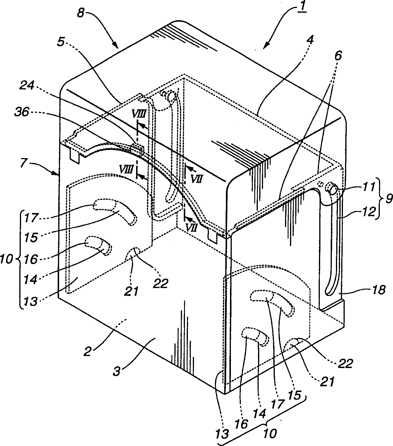
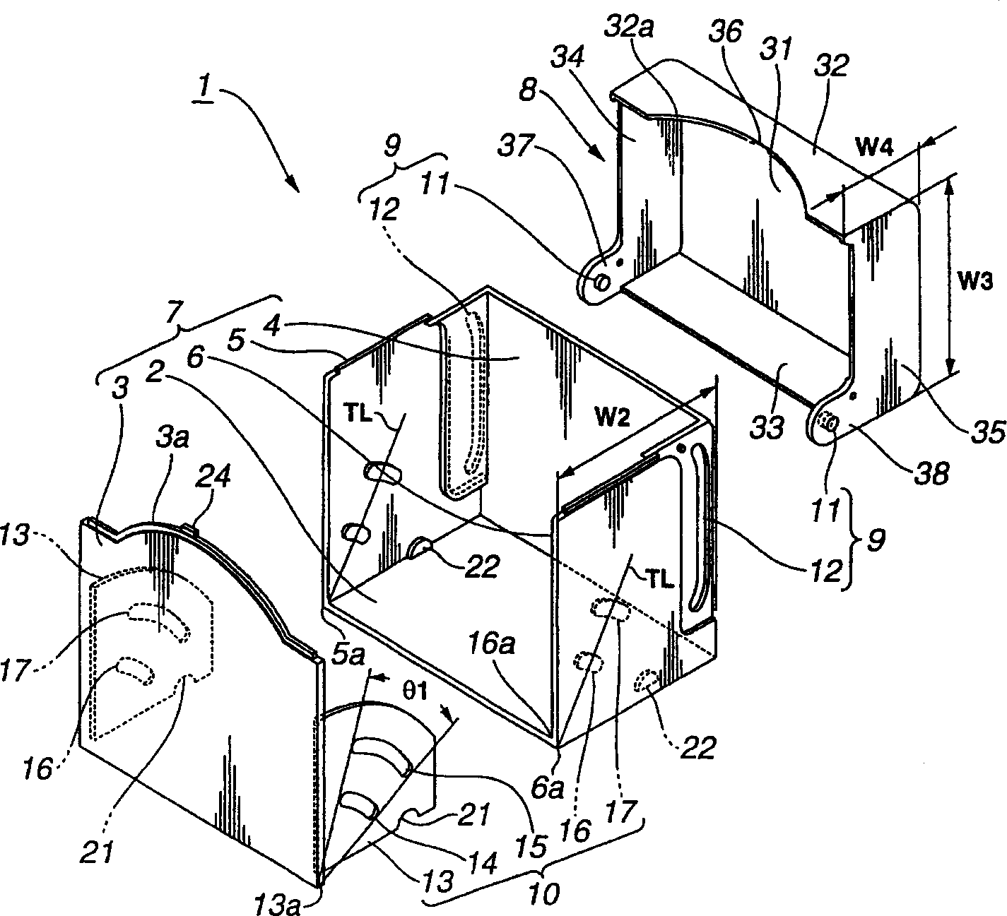
[0030] figure 1 It is a perspective view of the storage box 1 of the present invention, figure 2 It is an exploded perspective view of the storage box 1. The storage box 1 includes a box body 7 , a cover 8 , a turning device 9 and a tilting device 10 . The box main body 7 includes a bottom panel 2 , a front panel 3 , a rear panel 4 , a right panel 5 and a left panel 6 . A front panel 3 , a rear panel 4 , a right panel 5 and a left panel 6 are mounted on four sides of the bottom panel 2 so as to surround the bottom panel 2 . Rotating means 9 are provided to rotatably mount (open or close) the cover 8 to the box body 7 . The tilting device 10 tilts the front panel 3 forward, thereby expanding the opening of the box main body 7 .

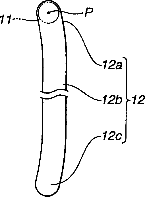
[0031] The rotating means includes a pair of rotating shafts 11 mounted on the cover 8, and a pair of support portions 12 mounted on the box main body 7. As shown in FIG. The support portion 12 is formed as an elongated slot so that the rotary s...


PUM


Abstract

A storage case is comprised of a case main body, a cover, a rotating means and a tilt means. The case main body has a bottom plate, the front plate, a back plate, a right plate and a left plate which are arranged so that the front, back, right and left plates surround four sides of the bottom plate. The cover is installed to the case main body so as to open and close an opening of the case main body. The rotating means swingably and slidably connects the cover with the case main body. The rotating means has a rotation shaft installed to the cover and a bearing portion installed to the case main body. The bearing portion is formed into an elongate groove extending in a vertical direction of the case main body. The front plate is tilted forward by the tilt means.

Description

technical field [0001] The present invention relates to a storage case preferably for storing information storage media, hereinafter referred to as disks, such as magnetic disks and optical disks. Background technique [0002] Figure 19 and 20 A known disc storage case 101 is shown for storing a plurality of discs. The disc storage case 101 includes a case main body 107, a cover 108 for opening and closing the opening of the case main body 107, and a rotating device 109 for rotatably mounting the cover 108 on the case main body 107. The box main body 107 includes a bottom panel 102 , a front panel 103 , a rear panel 104 , a right side panel 105 , and a left side panel 106 provided on four sides of the bottom panel 102 so as to surround the bottom panel 102 . [0003] Such as Figure 21 As shown, the rotating device 109 includes a rotating shaft 110 mounted to the box body 107 and a support portion mounted to the cover 108 . The rotating shaft 110...

Claims


Application Information

Patent Timeline
Patent Type & Authority Applications(China)
IPC IPC(8): B65D85/57B42F7/14B65D43/16G11B23/023
CPCB42F7/145B65D85/544
Inventor 菊地修一伊豆利惠
Owner SONY CORP
Why Eureka
Try Eureka