
Steering column collision absorbing structure

A technology of shock absorption and steering column, which is applied to steering column, steering mechanism, steering control, etc., and can solve the problem of reduced degree of freedom of surrounding components

Inactive Publication Date: 2003-03-12
MITSUBISHI MOTORS CORP +1
View PDF1 Cites 2 Cited by
  • Summary
  • Abstract
  • Description
  • Claims
  • Application Information

AI Technical Summary

Problems solved by technology

Therefore, there is such a disadvantage that the degree of freedom in the design of the corresponding surrounding parts is reduced.

Method used


Image

  • Steering column collision absorbing structure
  • Steering column collision absorbing structure
  • Steering column collision absorbing structure

Examples


Embodiment Construction

[0022] DETAILED DESCRIPTION OF THE PREFERRED EMBODIMENT

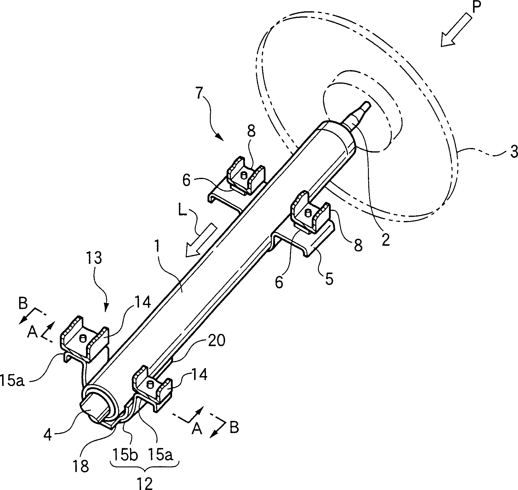
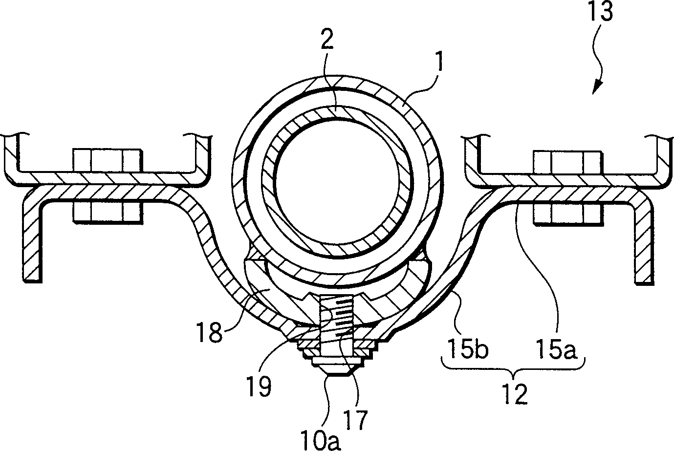
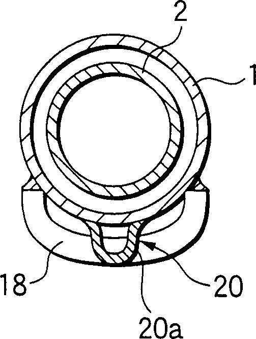
[0023] Refer below figure 1 to 5 illustrate embodiments of the present invention.

[0024] figure 1 is a schematic diagram of a steering column device mounted on an automobile, wherein reference numeral 1 denotes a steering column made of a thin pipe.

[0025] The steering column 1 is disposed in an oblique posture in front of a driver's seat (not shown), and is configured in such a posture that its end facing the vehicle rear side points upward and its end facing the vehicle front side points downward.

[0026] A steering shaft 2 is fitted in the steering column 1 so as to freely rotate. The steering wheel 3 is connected to the end of the steering shaft 2 protruding from the upper end of the steering column 1 . A universal joint 4 (partially shown) connected to a steering mechanism (not shown) is connected to the end of the steering shaft 2 protruding from the lower end of the steering column 1 .

[0027] The up...


PUM


Abstract

In an impact absorbing structure of a steering column, in order to fix the steering column to a vehicle body side bracket from the under side of the steering column, a rail-shaped guide member is formed so as to continue to the vehicle rear side end portion of a column side bracket. The guide member is protrusively provided at the under portion of the steering column and extends in the backward direction of the vehicle at an almost same height as that of the column side bracket. After the column side bracket passes the vehicle body side bracket, the guide portion guides the steering column so that the steering column having moved from the vehicle body side bracket is directed in the axial direction while maintaining its posture as it is.

Description

technical field [0001] The present invention relates to an automobile-mounted steering column shock absorbing structure for absorbing re-collision shock. Background technique [0002] In an automobile, when a passenger collides with the steering wheel (re-collision) or the airbag provided in the steering wheel is released to apply a predetermined value or greater impact force, the thin-walled tube steering column connected to the vehicle body (including the steering column inserted into the steering column) shaft) moves along the front of the vehicle, thereby mitigating the impact load. [0003] As a structure for connecting the steering column, there is a structure for fixing the steering column to the side of the vehicle body by using a bolt member, which is advantageous in many respects in that it is simple in structure, light in weight, and can be easily carried out as compared with other structures. In particular, the structure serves to support the underside of the st...

Claims


Application Information

Patent Timeline
IPC IPC(8): B60R21/05B62D1/19
CPCB60Y2410/102B62D1/184B62D1/195
Inventor 志田敏康天野刚志横田义则近藤真一
Owner MITSUBISHI MOTORS CORP
Learn More