Camera
A camera and lighting state technology, applied to TV, color TV parts, TV system parts, etc., can solve the problem of superior real-time shooting
- Summary
- Abstract
- Description
- Claims
- Application Information
AI Technical Summary
Problems solved by technology
Method used
Image


Examples
no. 1 Embodiment approach
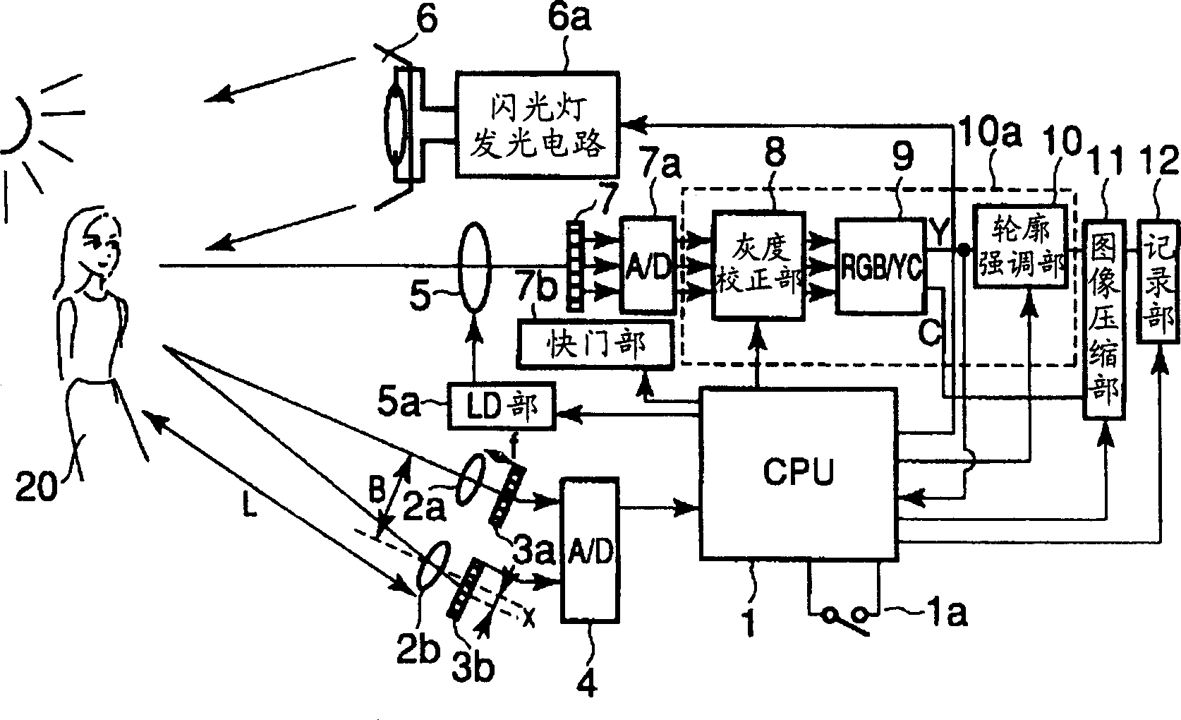
[0034] figure 1 It is a block diagram showing a camera according to an embodiment of the present invention. The image of the subject 20 enters the imaging unit 7 through the photographing lens 5 . In addition, the imaging unit 7 corresponds to "imaging means" described in the claims. The imaging unit 7 divides the incident image of the subject 20 into three color components (that is, RGB components) and integrates them, and outputs the integrated amount corresponding to each color component to an analog / digital (A / D) signal as a subject image signal. D) Conversion section 7a. The A / D conversion unit 7a converts the input integral output into a digital quantity, and outputs it to the image processing unit 10a.
[0035] The digital integral output (hereinafter referred to as image data) input to the image processing unit 10 a is first subjected to gradation correction in the gradation correction unit 8 . The gradation correction at this time is so-called gamma (γ) conversion...
no. 2 Embodiment approach
[0070] Below, refer to Figure 10 , and the second embodiment of the present invention will be described. In addition, the second embodiment of the present invention does not provide the sensor arrays 3a, 3b, etc., which are distance measuring devices, but uses the imaging unit, which is an imaging unit provided in a digital camera, or the like. figure 1 The imaging unit 7 performs distance measurement. In addition, the CPU 1 of the second embodiment includes the functions of "illumination state judging means" and "control means" described in the claims. In addition, other configurations and operations thereof are the same as those of the above-mentioned first embodiment, and thus description thereof will be omitted.
[0071] Figure 10 It is a flowchart showing operation control before shooting with a camera according to the second embodiment of the present invention. In addition, the operation after this flowchart is the same as Figure 8 The operations after step S4 ar...
no. 3 Embodiment approach
[0078] refer to Figure 12 to Figure 15 , the third embodiment of the present invention will be described. In addition, the configuration of the third embodiment can be applied to the configuration of the first embodiment or the second embodiment described above.
[0079] First, refer to Figure 13 (A), Figure 13 (B) describes the case where the background and the person who is the main subject are both controlled to have appropriate brightness when the strobe light emission control is performed in a backlit state.
[0080] Figure 13 (A) shows the temporal change of the integrated amount of the background subject after the strobe light is fired. At this time, the flash light cannot reach the background subject. However, because it is originally in a backlight state, even with only fixed light components such as natural light, it is possible to expose the background subject at an appropriate level at an appropriate exposure time.
[0081] also, Figure 13 (B) shows the...
PUM
 Abstract
Description
Claims
Application Information