Explosion proof method of close region of explosion

A near area, explosion-proof box technology, applied in the direction of blasting, aircraft parts, aircraft indicating devices, etc., can solve the problems of high cost, inconvenient use of explosion-proof measures, etc., achieve light weight, small size, and solve the limitations of the scope of use Effect

Inactive Publication Date: 2004-07-21
INST OF MECHANICS - CHINESE ACAD OF SCI +1
View PDF1 Cites 4 Cited by
  • Summary
  • Abstract
  • Description
  • Claims
  • Application Information

AI Technical Summary

Problems solved by technology

[0003] The purpose of the present invention is to overcome the disadvantages of inconvenient use and high cost of conventional anti-explosion measures, as well as the limitations on the scope of use, thereby providing a device with the ability to quickly and conveniently wrap pre-explosives, prevent or reduce the impact on explosions. Method of protection against explosions in the vicinity of explosions against damage to persons and objects in the area

Method used


Image

  • Explosion proof method of close region of explosion
  • Explosion proof method of close region of explosion

Examples


Embodiment 1

[0027] refer to figure 1 , the explosion-proof method that the present invention can be used in such an explosion near area of ​​the civil aviation cabin is described in detail:

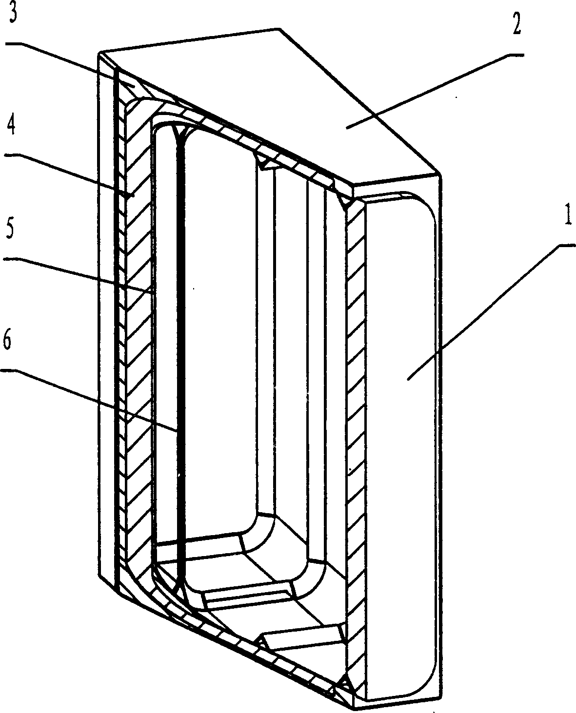
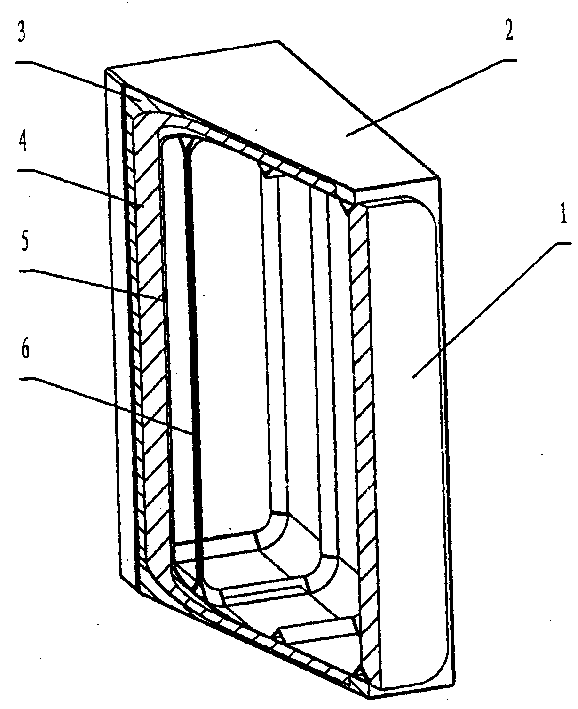
[0028] 1. Prepare in advance the components of the explosion-proof box used in the near area of ​​the explosion (such as figure 1 shown), placed at the predetermined position, the parts include:

[0029] (1) adopting a metal plate with a thickness of 1mm-4mm to make the shell 5, which is in the shape of a square tube with two ends open, with a length of 800mm, a width of 215mm, and a height of 660mm;

[0030] (2) mining thickness is that 20 millimeters of closed-cell polyurethane materials make a porous material layer 3, and its shape is the square tube shape of two ends opening, and its length is 800 millimeters, and width is 220 millimeters, and height is 680 millimeters; Better tensile strength, larger elongation thickness is 25 millimeters of rubber to make a lightweight material layer 4, and i...

Embodiment 2

[0037] Such as figure 1 Shown, on the basis of embodiment 1, increase a step (4) adopt 0.5 millimeter thick aluminum plate to make a height be 750 millimeters, width is 305 millimeters, the decorative shell 2 that length is 800 millimeters, and this shell is enclosed within Outside the porous material layer 3, it is positioned at the outermost layer of the box body. It is usually used as a dining car in the aviation cabin. It is beautiful, does not take up space, and has one more layer of explosion-proof measures.

[0038] In this example, the closed-cell polyurethane material is prepared from isocyanate, combined polyether and metal powder; among them, the isocyanate is dimethylmethane diisocyanate isomer, and the combined polyether has a density of 200kg / m 3 , the closed cell rate is 95%, and the polyurethane material with a pore size of 0.1mm is compressed with a compressive strength of 600kPa. The metal powder is copper powder with a particle size of 60 microns. The weight...

Embodiment 3

[0040] On the basis of Example 1, the shell bladder made of steel plate in step (1) is replaced by shell shell 5 made of composite material, and several ribs 6 are added on the inner surface of shell shell 5 to strengthen the shell The rigidity of the tube 5 is to better achieve the purpose of vacuuming, reduce the impact strength of the explosion itself, and reduce the strong noise of the explosion, so as to ensure that the side of the tube of the shell tube 5 will not leak high-speed debris outward, ensuring flight safety .


PUM


Abstract

An anti-explosion method for the explosive in the near explosion region features that an anti-explosion case is used, which has two opposite gates made of the closed-pore porous material and a sealed vacuumizing tube communicated with a vacuumizing pump. After the explosive is put in said anti-explosion case, said two gates are opened and the vacuumizing pump is turned one. When the explosive is detonated, the explosion pressure is symmetrically released via opposite two gates and the shock energy is absorbed by vacuum space and the absorptive layer in case.

Description

technical field [0001] The invention relates to an explosion-proof method, in particular to an explosion-proof method used in the explosion near zone. technical background [0002] In the case that explosives need to be detonated, the usual explosion-proof method is to place the explosives in a sealed cavity, that is, detonate in an anti-explosion object, reduce the impact of the explosion on the outside, and reduce the damage caused by the explosion, as shown in the Chinese patent publication Described in CN1071132A, the defect of this method is: it takes too long to vacuumize the cabin, and there are many difficulties in applying it to the passenger cabin of civil aviation, which cannot meet the actual needs. Another method is to effectively control the explosion by increasing the size of the internal cavity of the anti-explosion object and increasing the strength and thickness of the anti-explosion object, which will lead to an increase in the volume, strength and thickne...

Claims


Application Information

Patent Timeline
Patent Type & Authority Applications(China)
IPC IPC(8): B64D25/00B64D45/00F42D5/04
Inventor 陈力李海丁雁生李敬王彦军栗牧怀向长美梁建李德聪
Owner INST OF MECHANICS - CHINESE ACAD OF SCI
Why Eureka
Try Eureka