Magnetic recording head and magnetic disc storage apparatus mounting the magnetic head

A recording magnetic head and magnetic head technology, applied in the configuration/installation of recording head, magnetic recording head, recording information storage and other directions, can solve the problems of high recording density and obstacles of magnetic transition pattern

Inactive Publication Date: 2004-12-01
HITACHI GLOBAL STORAGE TECH JAPAN LTD
View PDF1 Cites 3 Cited by
  • Summary
  • Abstract
  • Description
  • Claims
  • Application Information

AI Technical Summary

Problems solved by technology

In addition, the curvature of the magnetic-transition pattern in the recording bit-cell poses an obstacle to achieve higher recording densities

Method used


Image

  • Magnetic recording head and magnetic disc storage apparatus mounting the magnetic head
  • Magnetic recording head and magnetic disc storage apparatus mounting the magnetic head
  • Magnetic recording head and magnetic disc storage apparatus mounting the magnetic head

Examples


Embodiment Construction

[0039] Hereinafter, the present invention will be explained by means of embodiments with reference to the drawings.

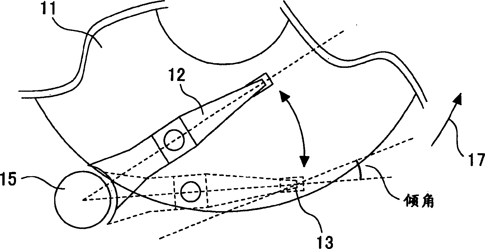
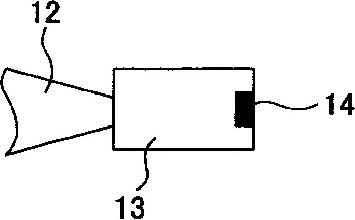
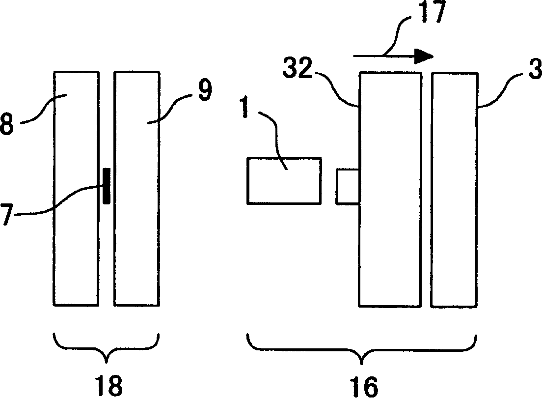
[0040] Figure 1A An example of the magnetic disk device according to the present invention is schematically shown. Figure 1B It is an enlarged view of the head slider part of the magnetic disk device. Figure 1C Observed from the surface of the magnetic head air bearing (airbearing) Figure 1B Enlarged view of the head part of.

[0041] The magnetic disk device uses the magnetic head 14 to perform recording and reproduction of the magnetization signal on the magnetic disk 11 rotating in the arrow 17 direction. The magnetic head 14 is mounted on a magnetic head slider 13, and the magnetic head slider 13 is fixed on the end of a cantilever 12 rotated by a rotary actuator 15. The magnetic head 14 is composed of a recording magnetic head 16 and a reproducing magnetic head 18. The reproduction head 18 includes a reproduction element 7 provided between a lower shield ...


PUM

PropertyMeasurementUnit
saturation flux densityaaaaaaaaaa

Abstract

A magnetic field distribution of a recording head is made linear so that a curvature of the magnetic-transition pattern in recording bit cells can be corrected. In a SPT head having a main pole 1 and an auxiliary pole 3, a magnetic layer 32 is disposed on a trailing side of the main pole. The magnetic layer is provided with a protruding portion 32a protruding towards the main pole. A width Nw of a side of the protruding portion opposite the main pole of the protruding portion is made smaller than a width Tww of the main pole on the trailing side.

Description

Technical field [0001] The present invention relates to a magnetic head suitable for perpendicular magnetic recording, a method of manufacturing the magnetic head, and a magnetic disk device in which the magnetic head is mounted. Background technique [0002] In magnetic disk devices, magnetic heads are used to read and write data on recording media. In order to increase the recording capacity per unit area on the magnetic disk, the areal density must be increased. However, in the current longitudinal recording system, when the length of the recorded bit is reduced, the areal density cannot be increased due to the thermal fluctuation of the magnetization in the medium. In order to solve this problem, a perpendicular recording system is proposed, by means of which the magnetization signal is recorded in a direction perpendicular to the medium. [0003] There are two types of perpendicular magnetic recording. One uses a double-layer perpendicular magnetic recording medium containin...

Claims


Application Information

Patent Timeline
Patent Type & Authority Applications(China)
IPC IPC(8): G11B5/31G11B5/00G11B5/012G11B5/09G11B5/127G11B5/187G11B5/23G11B5/48
CPCG11B5/012G11B5/1278G11B5/23G11B5/09G11B5/4886G11B2005/0029G11B5/1871
Inventor 望月正文中村敦江藤公俊
Owner HITACHI GLOBAL STORAGE TECH JAPAN LTD
Why Eureka
Try Eureka