Endoscope

A technology for endoscopes and insertion parts, applied in the field of endoscopes, can solve problems such as inability to perform correct bending, inability to perform, fatigue deformation, etc., and achieve the effect of low manufacturing cost

Inactive Publication Date: 2015-05-27
FUJIFILM CORP
View PDF11 Cites 0 Cited by
  • Summary
  • Abstract
  • Description
  • Claims
  • Application Information

AI Technical Summary

Problems solved by technology

[0004] In the endoscope described in Japanese Patent Laid-Open No. Hei 9-238895, since there are many components with complex shapes, for example, a complex-shaped fixing member formed with a plurality of grooves and a U with grooves engaged with the fixing member are used. The base of the letter-shaped brake, etc., so there are disadvantages such as increased cost
[0005] In addition, since the shape of the fixing part is a shape with a large processing workload, the length of the fixing part is restricted, and the adjustment range of the position adjustment of the fixing part relative to the base is also limited.
Moreover, since the pitch of the grooves of the fixing member determines the accuracy of the position adjustment of the fixing member relative to the base, it is impossible to perform fine position adjustment beyond the pitch of the grooves, and it is possible that abnormal force is applied to the guide screw and the fixing member. assembled
At this time, due to the fatigue deformation of the guide screw, there is a problem that the correct bending operation cannot be performed.

Method used


Image

  • Endoscope
  • Endoscope
  • Endoscope

Examples


Embodiment Construction

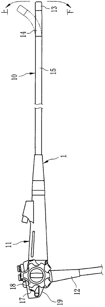
[0015] figure 1 Among them, an electronic endoscope 1 includes an insertion unit 10 inserted into the body, an operation unit 11 for operating the insertion unit 10 , and a universal cord 12 extending from the operation unit 11 . The insertion part 10 has a front end rigid part 13 , a freely bendable bending part 14 and a flexible flexible part 15 . The flexible part 15 has a length of, for example, about 2 m so that the distal rigid part 13 reaches a desired observation site in the body.

[0016] As is well known, the front end rigid portion 13 has built-in imaging elements such as an objective lens, a CCD, and a CMOS image sensor. The image of the observation site in the body is formed on the imaging element through the objective lens. The imaging element converts an optical image into an electrical signal. An imaging signal from the imaging element is sent to the operation unit 11 through a signal cable inside the insertion unit. Then, it is transmitted to a processor d...


PUM


Abstract

PROBLEM TO BE SOLVED: To form a fixed member in comparatively simple shape and to maintain accurate curve operation in an endoscope. SOLUTION: A guide member 30 includes a base part 41, a support member 42, fixed members 43-46 and guide pipes 47-50. The ends of guide screws 51-54 are fixed to the ends 47a-50a of the guide pipes 47-50. The opening edges of holes 43a-46a of the fixed members 43-46 and the opening edges of the guide pipes 47-50 are chamfered beforehand. The guide pipes 47-50 are positioned so that the pulley side opening positions of the guide pipes 47-50 are located inside the holes 43a-46a of the fixed members 43-46. The guide screws 51-54 stop the positions of the guide pipes 47-50 in a state of not being over-extended and over-loose in insertion parts, and molten solder is poured into solder holes 43e-46e. When the solder is solidified, the guide pipes 47-50 are fixed to the fixed members 43-46. COPYRIGHT: (C)2012,JPO&INPIT

Description

technical field [0001] The present invention relates to an endoscope, and more specifically, to a fixing structure for a guide tube guiding an operating wire for changing the direction of a distal end. Background technique [0002] The endoscope includes an insertion unit inserted into the body and an operation unit for operating the insertion unit. The insertion part is sequentially composed of a front end rigid part, a curved part and a flexible part from the front end. An objective lens, a solid-state imaging device such as a CCD, an illumination lens, and the like are provided on the distal end rigid portion. In order to protect each lens or solid-state imaging element, the front-end hard part is made of hard resin material and is made into the cylindrical shape with the front-end side closed. The bending part is a plurality of joint members connected in a cylindrical shape. By turning the operation button provided on the operation part, pulling the operation steel wi...

Claims


Application Information

Patent Timeline
Patent Type & Authority Patents(China)
IPC IPC(8): A61B1/005
Inventor 奥雅俊
Owner FUJIFILM CORP
Why Eureka
Try Eureka