Method for laser straightening guide rail

A guide rail and laser technology, applied in laser welding equipment, optical devices, linear motion bearings, etc., can solve problems such as difficult automation

Active Publication Date: 2021-02-02
ROBERT BOSCH GMBH
View PDF7 Cites 0 Cited by
  • Summary
  • Abstract
  • Description
  • Claims
  • Application Information

AI Technical Summary

Problems solved by technology

The disadvantage of this method is that it is difficult to automate

Method used


Image

  • Method for laser straightening guide rail
  • Method for laser straightening guide rail
  • Method for laser straightening guide rail

Examples


Embodiment Construction

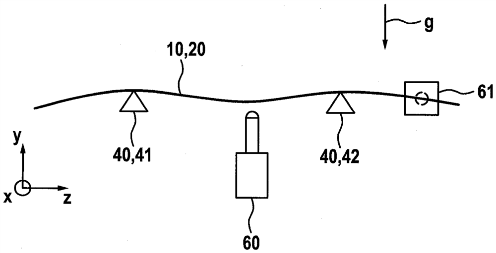
[0032] figure 1 A roughly schematic side view of the blank 20 accommodated in the holding device 40 is shown. The fixing device 40 comprises a first and a second support 41 , 42 which are spaced apart from each other in the direction of the longitudinal direction z. Two corresponding point-shaped bearing points define the longitudinal axis z . The blank 20 is placed on the first and second supports 41 , 42 , wherein due to the effect of gravity g the blank is bent approximately as currently shown, wherein the bend is shown exaggerated. The distance between the two supports 41 , 42 is preferably selected in accordance with the length of the blank 20 to be processed such that as little elastic deformation as possible occurs due to the force of gravity. The blank 20 is preferably firmly clamped on the two supports 41 , 42 so that it cannot move. The clamping is preferably carried out in such a way that no further hindrance to the bending of the blank 20 due to the force of gra...


PUM


Abstract

The invention relates to a method for producing a guide rail (10) for a linear rolling bearing. According to the invention, the method comprises the following steps carried out in the given sequence:a) producing a blank (20) of the guide rail (10) from steel; b) inserting the blank into a holding device (40) such that the blank (20) is held in a stationary manner; c) measuring (60) the blank (20)held in the holding device (40), wherein deviations from a linear shape are measured at a plurality of points along the longitudinal axis (z); d) irradiating the blank (20) held in the holding device(10) with a laser beam (53), the surface section (30) being irradiated with the laser beam (53) along the longitudinal axis (z) at a plurality of locations on each of two side surfaces (16) directedin opposite directions with respect to a first transverse axis (x) in such a way that the surface section is heated into a plastic region.

Description

technical field [0001] The invention relates to a method for producing a guide rail of a linear rolling bearing. Background technique [0002] A linear rolling bearing is known, for example, from EP 971 140 B1. A corresponding blank of the guide rail can be produced, for example, according to the method described in DE 10 2014 204 073 A1. Here, it may occur that, despite the highly precise grinding, the guide rails are not completely straight at the ends. A so-called 3-point straightening is usually used in order to bring about the desired straightness of the guide rail. In this case, the guide rail is placed on two supports spaced apart from one another in the direction of the longitudinal axis. Between the supports, pressure is applied to the guide rail, which is supported by the supports. In this case, the value of the pressure is selected such that a small plastic bending of the guide rail is achieved. The disadvantage of this method is that it is difficult to autom...

Claims


Application Information

Patent Timeline
Patent Type & Authority Applications(China)
IPC IPC(8): B23K26/352B23K26/354F16C29/00
CPCB23K26/352B23K26/354F16C29/00B23P15/003F16C29/04F16C29/005F16C29/004F16C2223/00G01B11/272G01B5/20G01B9/02G01B11/26Y10T29/49641
Inventor T.哈斯H.沙芬贝格尔S.富尔曼
Owner ROBERT BOSCH GMBH
Why Eureka
Try Eureka