Methods and instruments for interbody fusion

A fusion device and driving tool technology, applied in the field of spinal anatomical implants, can solve the problems of spinal imbalance, unacceptable, kyphotic deformation, etc.

Inactive Publication Date: 2005-11-30
SDGI集团有限公司
View PDF10 Cites 31 Cited by
  • Summary
  • Abstract
  • Description
  • Claims
  • Application Information

AI Technical Summary

Problems solved by technology

However, this method of over-reaming the posterior is generally not generally accepted due to the removal of the load-bearing bone in the spine and because it is generally difficult to ream the posterior portion of the lower lumbar region where the lordosis is greatest
In most cases where such implants are used, no effort is made to restore the lordotic arc, thus the cylindrical shape of the implant tends to induce kyphotic deformation as the vertebra stabilizes around the implant
This phenomenon throws the spine out of balance and often leads to reoperation

Method used


Image

  • Methods and instruments for interbody fusion
  • Methods and instruments for interbody fusion
  • Methods and instruments for interbody fusion

Examples


Embodiment Construction

[0032] In order to better understand the principle of the present invention, the present invention will be described below with reference to several embodiments shown in the drawings and using specific language. Nevertheless, it should be understood that this is not meant to limit the scope of the present invention, and those skilled in the art to which the present invention pertains will naturally expect changes and further improvements to the devices shown in the accompanying drawings, as well as those contained therein. Further Applications of the Principles of the Invention.

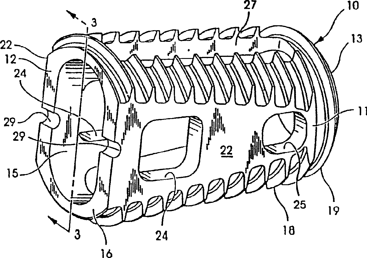
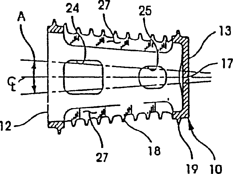
[0033] Figure 2-5 Shown is an intracorporeal fusion device 10 according to one aspect of the invention. The device consists of a rigid conical body 11 preferably made of a biocompatible or inert material. For example, body 11 may be made of medical grade stainless steel or titanium, or other suitable material having suitable strength characteristics as described above. The device can also be made...


PUM


Abstract

The invention relates to a driving tool for embedding the body fusion device to the clearance between the adjacent vertebras. The fusion device is provided with a body which is provided with a cylinder outer surface cut by a flat side wall arranged relatively. The outer surface is provided with an outside thread. The tool comprises a lathy axle and a pair of corresponding clamps connected with one end of the axle through an articulated piece. The clamp is separated from each other. Every clamp is provided with a pair of inward surfaces contacting the flat side wall arranged relatively to the fusion device and a pair of outward surfaces coherent to the outer surface of the cylinder of the fusion device.

Description

[0001] This application was submitted on March 26, 1996, the application number is 96105961.3, and the title of the invention is "In vivo fusion device and method for restoring the normal anatomical shape of the spine". technical field [0002] The present invention relates to an artificial implant for placement between vertebrae in the space left after the removal of a damaged intervertebral disc. Spinal fusion with implants that maintain or restore normal spinal anatomy at a specific vertebral level. Background technique [0003] Over the past few years, there has been a steady increase in the number of spinal surgeries performed to rule out causes of lower back pain. Most commonly, pain in the lower back is caused by damage or disease to the discs between adjacent vertebrae. These discs may herniate or undergo various degenerations, both of which disrupt the anatomical function of the discs. The most popular surgical approach to these conditions is to fuse the two verte...

Claims


Application Information

Patent Timeline
Patent Type & Authority Applications(China)
IPC IPC(8): A61B17/56A61B17/16A61B17/58A61B17/70A61B17/88A61FA61F2/00A61F2/28A61F2/30A61F2/44A61F2/46A61L27/00A61L27/22A61L31/04
CPCA61F2/442A61F2002/3085A61L31/047A61B17/8875A61F2220/0025A61F2002/3082A61F2002/30858A61F2310/00131A61F2230/0017A61F2/30744A61F2230/0004A61F2230/0067A61F2002/4641A61F2310/00095A61F2002/4475A61F2002/30874A61F2002/30143A61F2/4455A61F2002/30136A61B17/1671A61F2002/464A61F2002/30153A61F2002/30504A61L27/227A61F2002/30158A61F2002/3021A61F2002/30217A61F2310/00161A61F2310/00179A61F2002/30777A61F2002/448A61F2310/00017A61F2/4611A61F2/4637A61F2230/0019A61F2310/00023A61F2002/2835A61F2/446A61F2/30767A61F2230/0026A61F2002/30774A61F2310/00796A61F2002/30785A61F2002/305A61F2002/30593A61F2002/30873A61L2430/38
Inventor T·A·兹德布里克E·F·雷三世L·M·博伊德
Owner SDGI集团有限公司
Why Eureka
Try Eureka