
Patsnap Eureka
For R&D, Patsnap Eureka makes reading and utilizing patents & technical documents easy.
Patsnap Eureka AIR
Designed for self-driven R&D workflows. Generate viable solutions, solve complex R&D challenges, empower your innovation with AI.

Patsnap Eureka Materials
Designed for material experts only. Revolutionize your material R&D, from search, analyze, to developing new materials.

TechResearch
Generate reliable direction feasibility study reports for your R&D in just a few steps.

TechSeek
Discover and master advanced knowledge NOW. Basics, ideas, possibilities, all at once.

TechMind
As an expert in R&D Theories, TechMind can generates customized viable solutions instantly.

TechRisk
Analyze your overall solution with one click, know your potential R&D risks in advance.

TechMonitor
Get weekly tech updates, stay abreast of the latest tech innovations and key insights.
Disk player
A player, disc loading technology, applied in the direction of instruments, record carrier structural parts, driving/moving recording heads, etc., can solve problems such as clamp bending
- Summary
- Abstract
- Description
- Claims
- Application Information
AI Technical Summary
Problems solved by technology
Method used
Image

Examples
Embodiment Construction
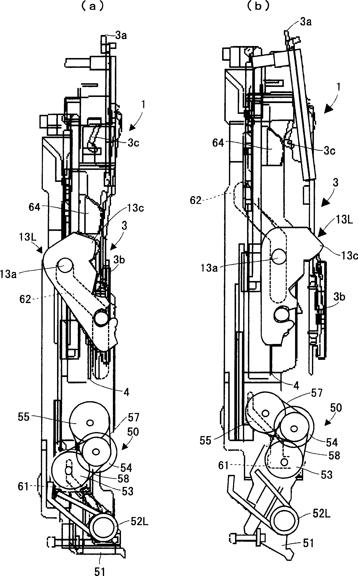
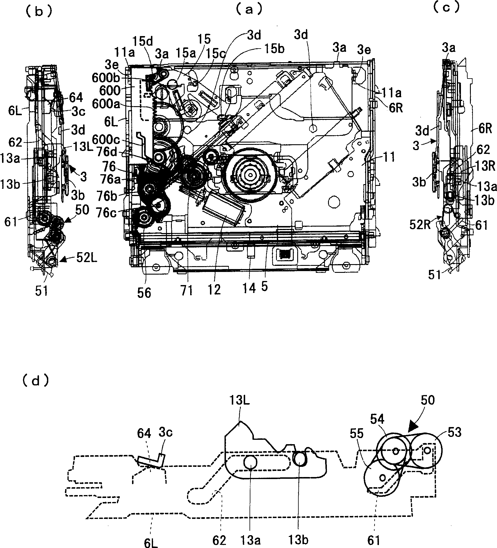
[0052] In the following, it will be based on Figures 1 to 13 Embodiments of the present invention are described.
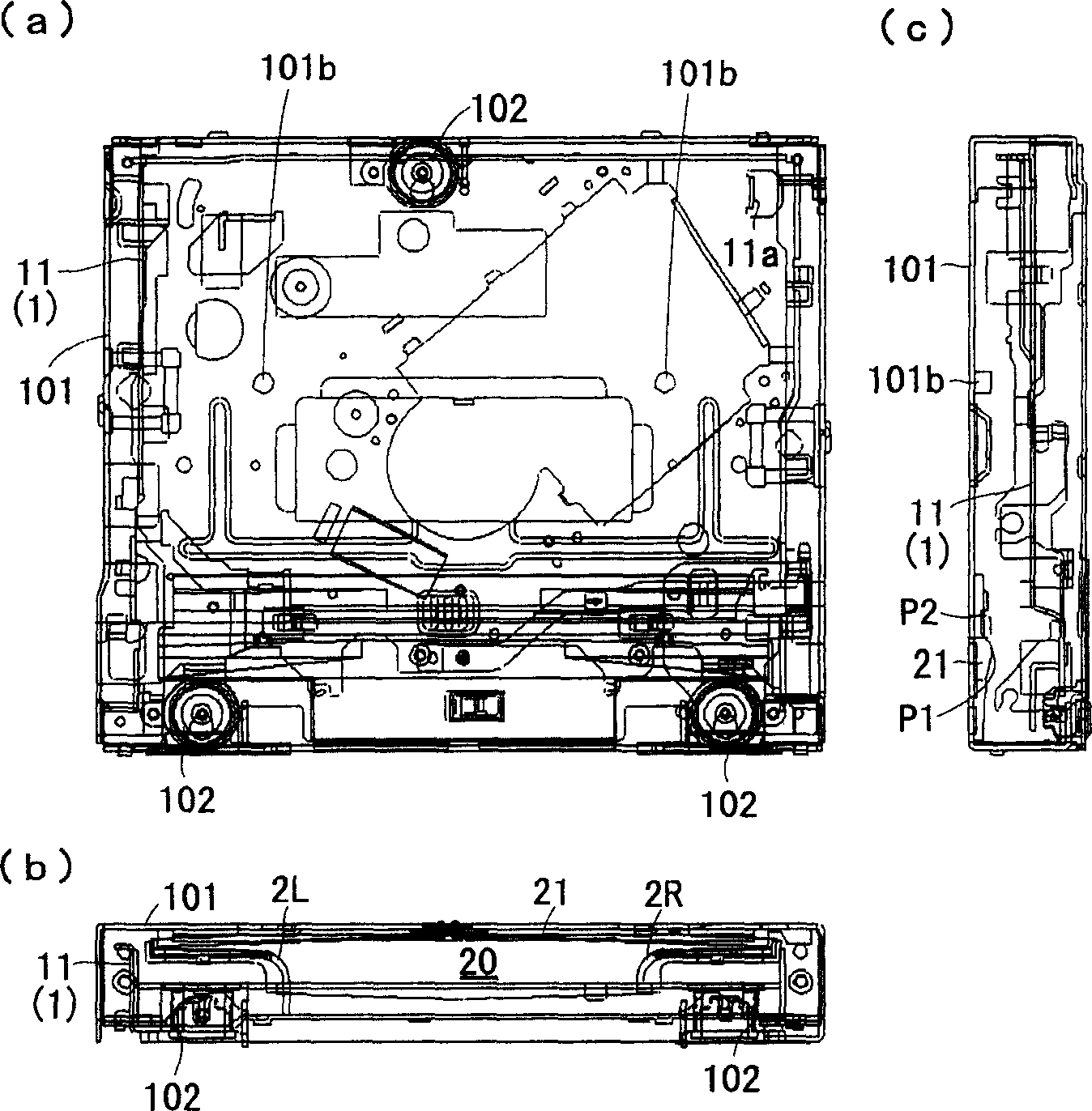
[0053] (Overview of disc player)
[0054] figure 1 Shows a view (chassis part) of a disc player, in which the display of different types of drive mechanisms is omitted. figure 1 (a) is a plan view, figure 1 (b) is the front view, and figure 1 (c) is a right side view. Disc player main body 1 (main body chassis 11 such as figure 1 shown) is arranged in the chassis base 101. The main body chassis 11 is elastically supported by coil spring dampers 102 (distributed at three positions) provided on the bottom surface end of the main body chassis 11 in the chassis base 101 . A disc loading slot 20 is formed on the front surface of the chassis base 101 . The disc loading slot 20 is provided with a right disc guide 2R and a left disc guide 2L formed of resin, and the disc loading slot 20 is shaped like a T-shape. The distance between the right end of the upper su...
PUM
 Abstract
Description
Claims
Application Information
 - R&D Engineer
- R&D Manager
- IP Professional
- Industry Leading Data Capabilities
- Powerful AI technology
- Patent DNA Extraction
Browse by: Latest US Patents, China's latest patents, Technical Efficacy Thesaurus, Application Domain, Technology Topic, Popular Technical Reports.
© 2024 PatSnap. All rights reserved.Legal|Privacy policy|Modern Slavery Act Transparency Statement|Sitemap|About US| Contact US: help@patsnap.com