Supercharge Your Innovation With Domain-Expert AI Agents!

Sensor system for tire

一种传感系统、轮胎的技术,应用在轮胎测量、轮胎零部件、测量装置等方向,能够解决传感器单元的电子部件损坏、误警报、无法发送信息等问题

Inactive Publication Date: 2006-04-19
THE YOKOHAMA RUBBER CO LTD
View PDF1 Cites 5 Cited by
  • Summary
  • Abstract
  • Description
  • Claims
  • Application Information

AI Technical Summary

Problems solved by technology

[0003] In such a sensor system for tires, since the sensor unit is arranged in the tire air chamber, there is a disadvantage that even if the sensor unit falls off from the prescribed mounting position during the rim assembly operation, it cannot be judged that the sensor unit has fallen off.
Also, if you drive with the sensor unit detached, the electronic parts of the sensor unit will be damaged, and there may be cases where information cannot be sent or a false alarm will be issued.

Method used


Image

  • Sensor system for tire
  • Sensor system for tire
  • Sensor system for tire

Examples


Embodiment Construction

[0017] Hereinafter, the configuration of the present invention will be described in detail with reference to the drawings.

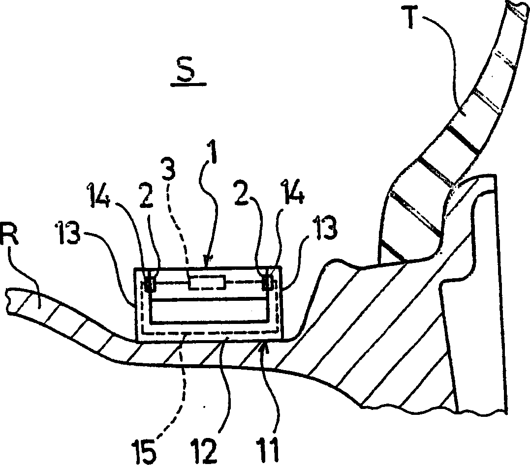
[0018] figure 1 It is a figure which shows the sensor system for tires comprised by the 1st Embodiment of this invention. exist figure 1 Among them, R is the rim, T is the tire, and S is the air chamber of the tire. The sensor device for a tire according to this embodiment includes a sensor unit 1 for detecting tire internal information and a base 11 for fixing the sensor unit 1 , and the sensor unit 1 is mounted in a tire air chamber through the base 11 .

[0019] The sensor unit 1 includes electronic components in a housing, measures the air pressure, internal temperature, and the like of the tire, and transmits the measurement results to the outside of the tire. The base 11 has at least a pair of locking portions 13 , 13 protruding from the bottom 12 , and the sensor unit 1 is clamped and locked by these locking portions 13 , 13 . The bottom 12 of...


PUM


Abstract

A sensor system for a tire, and the system enables the installation condition of a sensor unit in a tire's air chamber to be known. A sensor system where a sensor unit is installed in a tire's air chamber has detecting means for detecting a relative change in the distance between the sensor unit and a position where the sensor unit is installed.

Description

technical field [0001] The present invention relates to a tire sensor system for detecting tire internal information such as air pressure and temperature, and more specifically, to a tire sensor system capable of grasping the mounting state of a sensor unit in a tire air chamber. Background technique [0002] Conventionally, in order to monitor tire internal information such as air pressure and temperature, a sensor unit is generally installed on the inner surface of the tire or the groove of the rim, and the sensor unit detects the internal information of the tire, and then transmits the detection result to the An information receiving device on the outside of the tire (for example, refer to Japanese Patent Application Laid-Open No. 10-504783). [0003] In such a sensor system for tires, since the sensor unit is arranged in the tire air chamber, there is a disadvantage that even if the sensor unit falls off from the prescribed mounting position during the rim assembly opera...

Claims


Application Information

Patent Timeline
Patent Type & Authority Applications(China)
IPC IPC(8): B60C23/04G01L17/00
CPCB60C23/0408
Inventor 志村一浩
Owner THE YOKOHAMA RUBBER CO LTD
Features
  • R&D
  • Intellectual Property
  • Life Sciences
  • Materials
  • Tech Scout
  • Unparalleled Data Quality
  • Higher Quality Content
  • 60% Fewer Hallucinations
Learn More