Control member with a balance wheel and a planar spiral for a watch or clock movement

A technology of adjusting device and clock movement, applied in clocks, mechanical equipment, mechanically driven clocks, etc., can solve problems such as unsatisfactory angle belts, waste of time, etc.

Active Publication Date: 2006-05-31
PATEK PHILIPPE SA
View PDF1 Cites 19 Cited by
  • Summary
  • Abstract
  • Description
  • Claims
  • Application Information

AI Technical Summary

Problems solved by technology

However, according to the proponents of this proposal, although the horn bands in the center ring do significantly improve the isochronism of the balance spring assembly, the horn bands in the outer ring are not satisfactory
The proposer even ditched the hairspring with horn bands in the outer bezel, so believe they even wasted their time in this solution

Method used


Image

  • Control member with a balance wheel and a planar spiral for a watch or clock movement
  • Control member with a balance wheel and a planar spiral for a watch or clock movement
  • Control member with a balance wheel and a planar spiral for a watch or clock movement

Examples


Embodiment Construction

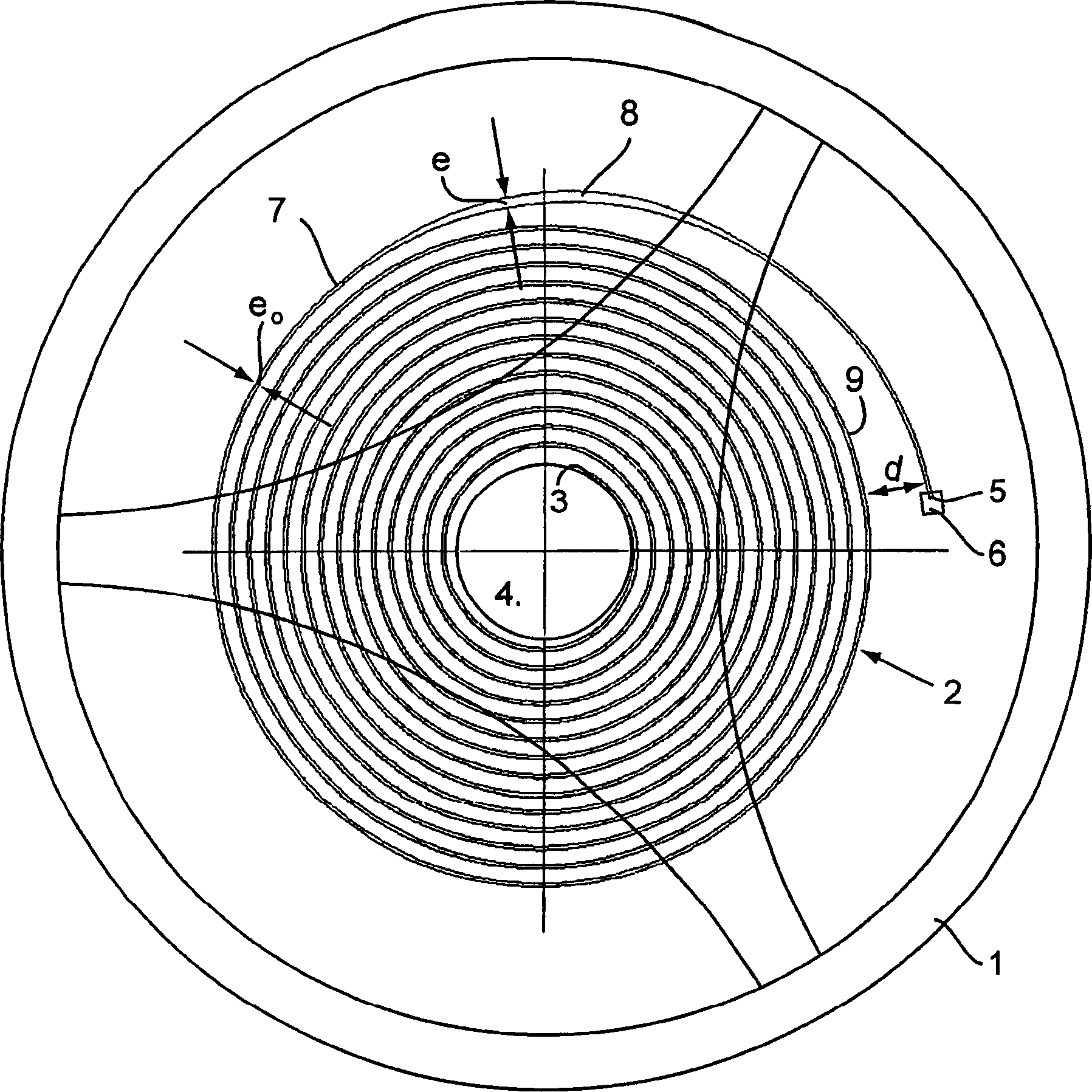
[0024] refer to figure 1 , the regulating device for a timepiece movement according to the invention comprises a balance wheel 1 and a planar hairspring 2 in the form of an Archimedean spiral. The inner end 3 of the balance spring 2 is fixed to the collet 4 driven by the shaft of the balance wheel 1 and is thus continuously subjected to the rotational torque of the balance wheel 1 . In a known manner, the rotating shaft of the balance spring assembly rotates in bearings (not shown). The outer end 5 of balance spring 2 is secured to a stationary part of the movement, in particular the balance-cock, by means of a securing member 6 called a "stud".

[0025] According to the invention, hairspring 2 has in its outer ring 7 reinforcements 8 arranged to enable substantially concentric deformation of the ring during expansion and contraction of hairspring 2 . This reinforcement 8 is achieved by making the thickness of a part of the strip forming the balance spring in the plane of th...


PUM


Abstract

Regulating device for a timepiece movement comprising a balance wheel (1) and a planar balance spring (2) comprising a balance spring (2) located in its outer ring (7) and arranged so that deformation of the ring substantially enables concentric reinforcement (8), characterized in that the spacing (d) between the terminal portion of the outer coil (7) of the hairspring (2) and the penultimate coil (9) is sufficiently large to allow expansion of the hairspring (2) The penultimate turn (9) can remain radially free up to an amplitude substantially corresponding to the maximum angle of rotation of the balance wheel (1) in the movement.

Description

technical field [0001] The invention relates to a regulating device with a balance wheel and a planar hairspring for a timepiece movement. Background technique [0002] It is known that the planar balance spring turns are deformed eccentrically when the balance spring is in operation. This eccentric deformation of the ring, ie the center of gravity of the hairspring not coincident with the center of rotation of the balance spring assembly, interferes with the setting of the balance spring assembly and makes it non-isochronous. [0003] The center of gravity of the hairspring is shifted to return at will to the center of rotation of the balance wheel, however this does not solve the problem because during the operation of the hairspring the center of gravity moves and therefore no longer coincides with the original center of gravity. [0004] Two different proposals have been proposed to make the center of gravity and the center of rotation coincide when the planar hairsprin...

Claims


Application Information

Patent Timeline
Patent Type & Authority Applications(China)
IPC IPC(8): G04B17/06F16F1/10F16F1/14
CPCF16F1/10F16F1/14G04B17/066
Inventor 让-皮埃尔·米西弗雷德里克·马耶尔米歇尔·贝洛
Owner PATEK PHILIPPE SA
Why Eureka
Try Eureka