
Interference ribs on surface of operating parts

A technology for operating parts and objects, applied in the field of friction ribs, which can solve the problems of false touch of burrs, false touch of keys, etc.

Inactive Publication Date: 2006-07-26
LITE ON IT
View PDF0 Cites 1 Cited by
  • Summary
  • Abstract
  • Description
  • Claims
  • Application Information

AI Technical Summary

Problems solved by technology

[0009] The object of the present invention is to completely eliminate the burrs at the end of the conflicting ribs by a conflicting rib arranged on the surface of an operating part. In addition to solving the aforementioned problem of false touches on the keys, it also solves the situation that various conflicting ribs have false touches on the burrs

Method used


Image

  • Interference ribs on surface of operating parts
  • Interference ribs on surface of operating parts
  • Interference ribs on surface of operating parts

Examples


Embodiment Construction

[0029] The invention relates to a conflicting rib arranged on the surface of the operating part. The operating part is pressed to make the conflicting rib press against an object adjacent to the end of the conflicting rib. In the embodiment, the button 30 is used as the operating component, the key column 32 is used as the conflicting rib, and the push switch 34 is used as the object to illustrate the present invention.

[0030] see Figure 4 and cooperate Figure 5 , Figure 4 It is a schematic bottom view of the button 30 and the key column 32 of the present invention. Figure 5 It is a schematic diagram of the lateral closure of the button 30, the key column 32 and the push switch 34 of the present invention. The present invention relates to a key post 32 disposed on the surface of a key 30. The key post 32 includes an interference structure 3202 and at least one auxiliary structure 3204 (there are two auxiliary structures 3204 in the figure). Wherein, the button 30 and...


PUM


Abstract

This invention relates to touch rib put onto the operation part composed of one touch structure and at least one assistant structure, wherein, The structure one end is connected to the operation part and the other end extracting to the outside to press the switch part; The assistant structure one end is connected to the operation part connected to the touch structure in one shape with the touch structure; the assistant structure length is shorter than the touch probe to make the other end of the assistant structure keep certain distance with the touch part.

Description

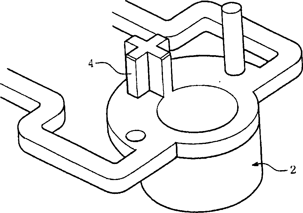
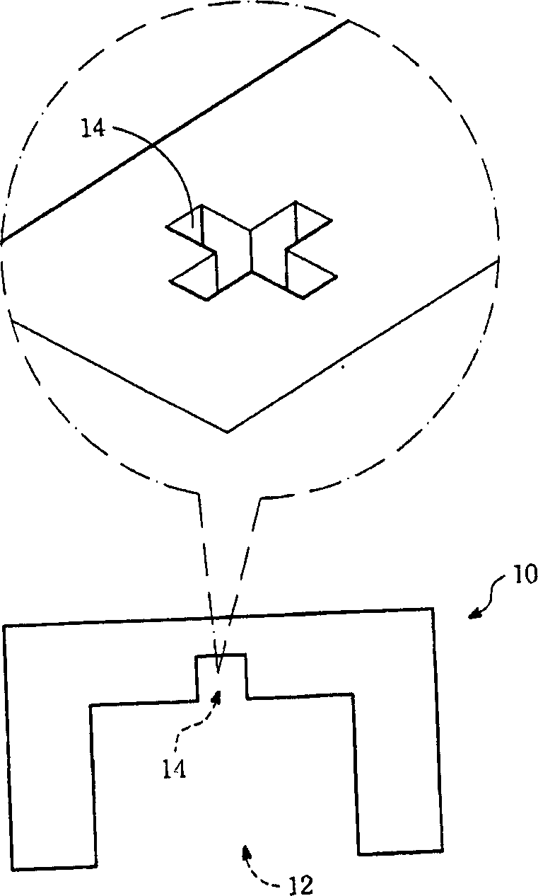
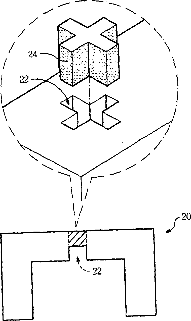
technical field [0001] The invention relates to a conflicting rib arranged on the surface of an operating component, especially the structural design of a key post arranged on the surface of a key. Background technique [0002] Whether it is an electronic product or other supplies in daily life, there are many items that need to be operated by pressing an operating part. For example, an operating part such as a push button is pressed against an object such as a push switch by means of a resisting rib such as a key post. [0003] see figure 1 , figure 1 It is a schematic bottom view of the button 2 in the known technology. A key column 4 is arranged on the bottom surface of the key 2, and a push switch (not shown) is arranged in the extension direction of the key column 4, and is adjacent to the end of the key column 4, and keeps a distance from the end of the key column 4 at ordinary times. When an external force presses the button from the top of the button 2, the press...

Claims


Application Information

Patent Timeline
Patent Type & Authority Applications(China)
IPC IPC(8): H01H13/14
Inventor 邱孟章曾继志
Owner LITE ON IT
Learn More