Anode clamp of pre-calcining anode electrolytic cell

A pre-baked anode and electrolytic cell technology, which is applied in the field of anode clamps for pre-baked anode electrolytic cells, can solve the problems of inconvenient use of pre-baked anode electrolytic cell anode clamps, inability to exert the mechanized advantages of small box clamps, and increased labor intensity of workers. , to achieve the effect of improving labor productivity, light weight and simple structure

A pre-baked anode and electrolytic cell technology, which is applied in the field of anode clamps for pre-baked anode electrolytic cells, can solve the problems of inconvenient use of pre-baked anode electrolytic cell anode clamps, inability to exert the mechanized advantages of small box clamps, and increased labor intensity of workers. , to achieve the effect of improving labor productivity, light weight and simple structure

CN1834296AActive Publication Date: 2006-09-20GUIYANG AL-MG DESIGN & RES INST

Image

  • Anode clamp of pre-calcining anode electrolytic cell

Examples


Embodiment Construction

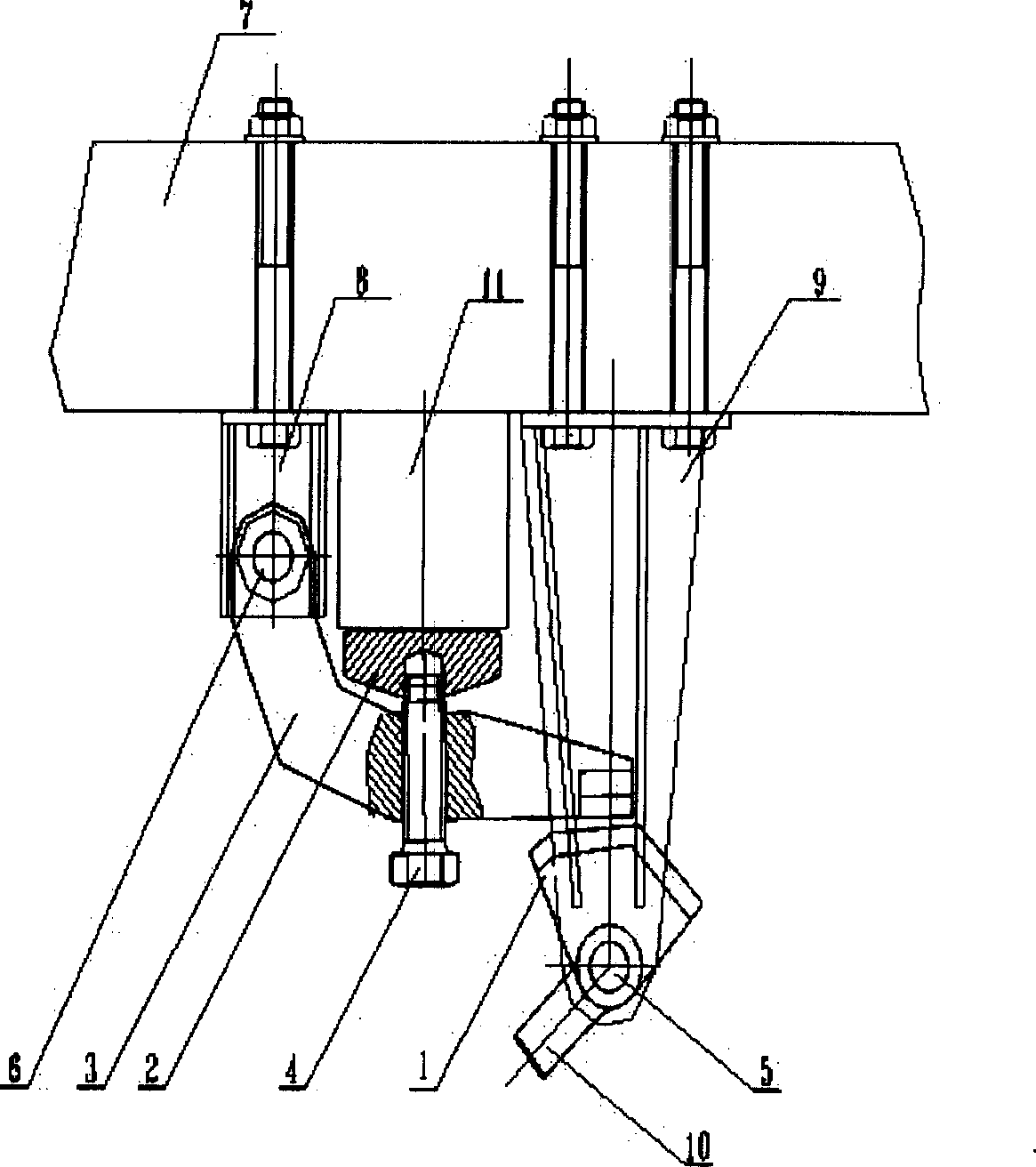
[0007] Embodiment of the present invention: on the existing aluminum electrolytic cell anode busbar (7), the upper left bracket (8) and the right bracket (9) are fixed by bolts, and the connecting rod shaft (6) is passed on the left bracket (8) Connect the upper connecting rod (3), the connecting rod (3) can be made into a straight rod shape or an L-shaped shape, and the adjusting bolt (4) and the adjusting bolt (4) can be installed on the connecting rod (3). press plate (2), then connect the manual eccentric wheel (1) through the eccentric wheel shaft (5) on the right bracket (9), and make the eccentric wheel surface of the manual eccentric wheel (1) and the connecting rod (3) The front end is contacted, and then an operating handle (10) is installed on the manual eccentric wheel (1).

[0008] The invention can be used in prebaked anode electrolyzers with different capacities, and is especially suitable for small prebaked anode electrolyzers as equipment for manually pressing...


PUM


Abstract

This invention discloses an anode jig for prebaked anodic aluminum reduction cells. Two supports are fixed on both sides of the aluminum reduction cell anode bus bar by bolts. A connecting rod is connected with the left support through a bearing, and the front end of the connecting rod is contacted with the face of a hand-operated eccentric wheel. This invention directly fixes a light anode jig with simple structure on the anode bus bar, thus can achieve the work of fastening-loosing the anode without the assistance from a multifunctional overhead traveling crane. This invention has such advantages as simple structure, low weight, easy operation, simple manufacturing process.

Description

Technical field: [0001] The invention relates to a prebaked anode electrolytic cell anode fixture for aluminum electrolytic cells, in particular to a prebaked anode electrolytic cell anode fixture for small aluminum electrolytic cells, belonging to the technical field of aluminum electrolytic cell anode fixtures. Background technique: [0002] At present, in the prior art, the equipment for pressing the anode of the electrolytic cell and the anode bus bar used on the aluminum electrolytic cell is mainly a small box clamp. Due to the heavy weight of the small box clamp, it must be used in conjunction with a multi-functional crane. Therefore, a high level of mechanization is required in use. However, for some electrolysis production workshops, especially for small prebaked electrolyzers, since the electrolysis workshop does not have a multi-functional overhead crane, this cannot give full play to the mechanized advantages of small box fixtures in the prior art, and must be ins...

Claims


Application Information

Patent Timeline
20 Sep 2006
Publication
CN1834296A
IPC
C25C3/12; C25C3/16
Inventors
陈鱖; 战慉棰