Stabilizer link and manufacturing method thereof

A manufacturing method and stabilizer technology, applied in the direction of connection, interconnection system, pivot connection, etc., can solve the problem of complicated structure of the fixture, and achieve the effect of preventing leakage

Active Publication Date: 2016-05-18
NHK SPRING CO LTD
View PDF12 Cites 0 Cited by
  • Summary
  • Abstract
  • Description
  • Claims
  • Application Information

AI Technical Summary

Problems solved by technology

[0022] However, in the manufacturing method proposed by the present applicant, since the forming mold uses a module different from the mold body, and the pressing portion of the radial surface of the module constitutes a part of the cavity, the method for installing the module on the subassembly Fixture structure is complex

Method used


Image

  • Stabilizer link and manufacturing method thereof
  • Stabilizer link and manufacturing method thereof
  • Stabilizer link and manufacturing method thereof

Examples


Embodiment Construction

[0053] (1) Each manufacturing process

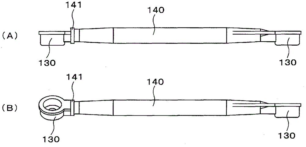
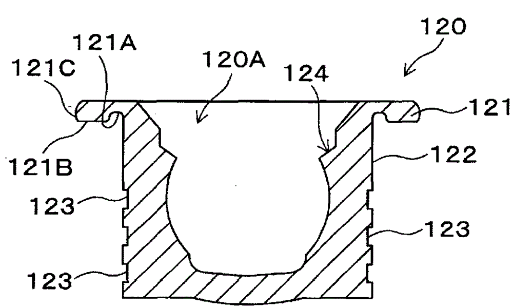
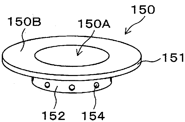
[0054] Hereinafter, an embodiment of the present invention will be described with reference to the drawings. Figure 4 (A)~ Figure 4 (D) is a side sectional view showing a partial structure of each step of the method of manufacturing the stabilizer link 100 according to the embodiment of the present invention. Figure 6 is included Figure 4 (C) An enlarged side cross-sectional view of a part of the ring member 150 shown in insert molding. Figure 6 Make the up and down direction and Figure 4 (C) On the contrary. Figure 12 It is a side view showing a rough structure of the ball stud 101 used in the embodiment. Figure 13 It is a side cross-sectional view showing a schematic structure of the ball seat 120 used in the embodiment.

[0055] The manufacturing method of the stabilizer link 100 of this embodiment and image 3Compared with the manufacturing method of the shown stabilizer link 200, there is a big difference in that the ...


PUM

PropertyMeasurementUnit
lengthaaaaaaaaaa

Abstract

To provide a stabilizer link and a method of manufacturing the same, which can effectively prevent resin from leaking to the outside while having a simple structure of a jig for attaching a molding die to a subassembly. The ring member (150) is used for insert molding, and the outer peripheral side (122) of the ball seat (120) of the subassembly (100) is brought into contact with the inner peripheral surface of the hole (150A) of the ring member (150). Press the outer radial surface (412B) of the fixed part (421) of the dust cover (401) toward the flange part (121) of the ball seat (120) through one side (150B) of the ring part (150), The fixing part ( 412 ) is sandwiched between one side ( 150B) and the flange part ( 121 ). The end portion (61A) of the mold body (61) is brought into contact with the other surface (150C) of the ring member (150).

Description

technical field [0001] The present invention relates to a stabilizer link including a housing and a support rod, and more particularly to an improvement in the manufacturing technology of an integrally molded resin housing and a support rod. Background technique [0002] The stabilizer link is the ball joint component that connects the suspension unit to the stabilizer unit. figure 1 It is a perspective view showing a schematic configuration of the front wheel side of the vehicle. The suspension device 10 is provided on the left and right tires 30 and includes a suspension arm 11 and a cylinder 12 . The lower end of the suspension arm 11 is fixed to a bearing portion of a shaft supporting the tire 30 , and the cylinder 12 is elastically displaceable with respect to the suspension arm 11 . A bracket 13 on which a stabilizer link 200 is mounted is provided on the suspension arm 11 . The suspension device 10 supports the weight of the vehicle body applied to the tires 30 . ...

Claims


Application Information

Patent Timeline
Patent Type & Authority Patents(China)
IPC IPC(8): F16C11/06B60G21/055
CPCF16C11/0657F16C11/0671B60G7/005B60G2204/1224B60G2204/416B60G2206/427B60G2204/42B60G2204/4404F16C11/0638F16C2326/05F16C11/0685Y10T29/4998Y10T403/32631B60G21/0551F16C11/0623
Inventor 黒田茂
Owner NHK SPRING CO LTD
Why Eureka
Try Eureka