Electrical power source, operational method of the same, inverter and operational method of the same

An operation method and technology of a power supply device, which are applied to emergency protection circuit devices, electrical components, single-network parallel feeding arrangements, etc., can solve the problems of power supply device cost increase, reliability reduction, and inability to prevent

Inactive Publication Date: 2006-11-22
ORIGIN ELECTRIC CO LTD
View PDF11 Cites 8 Cited by
  • Summary
  • Abstract
  • Description
  • Claims
  • Application Information

AI Technical Summary

Problems solved by technology

[0025] Furthermore, the countermeasures for preventing cross flow disclosed in the inventions of Patent Documents 5 to 11 require various complicated functions or circuits, which increases the cost of the power supply device, and at the same time, not only increases the siz

Method used


Image

  • Electrical power source, operational method of the same, inverter and operational method of the same
  • Electrical power source, operational method of the same, inverter and operational method of the same
  • Electrical power source, operational method of the same, inverter and operational method of the same

Examples


Embodiment approach 1

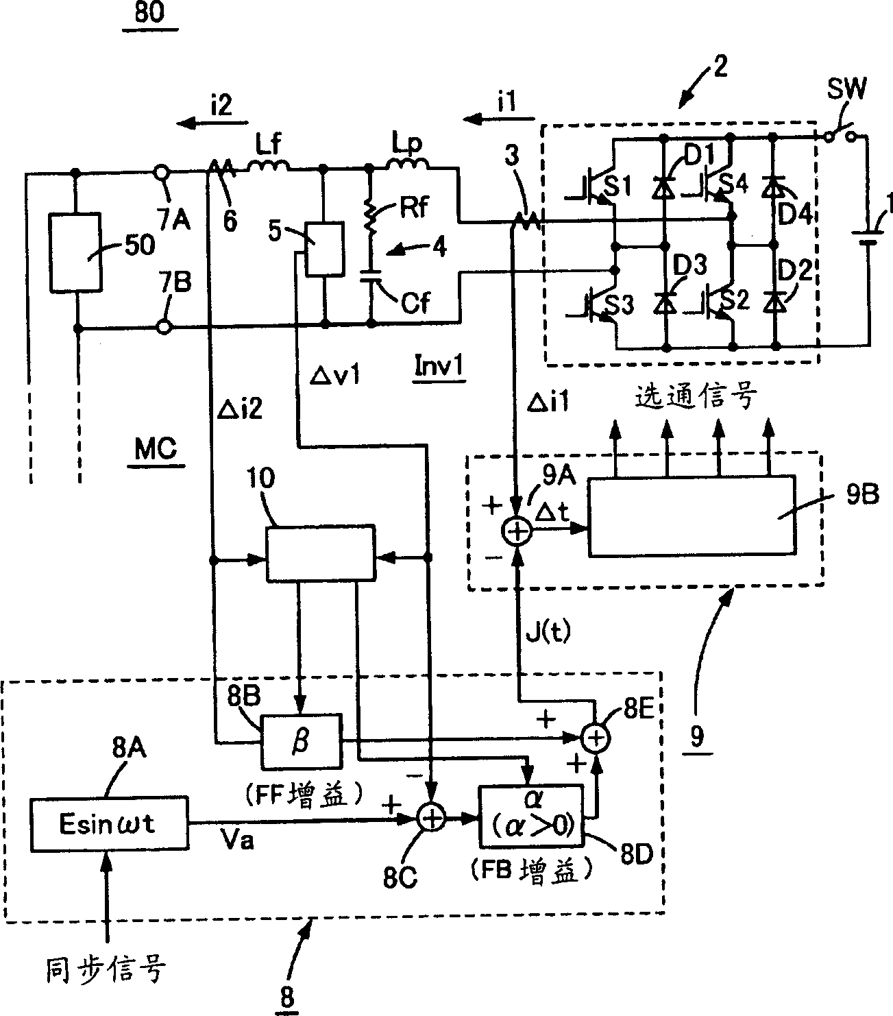
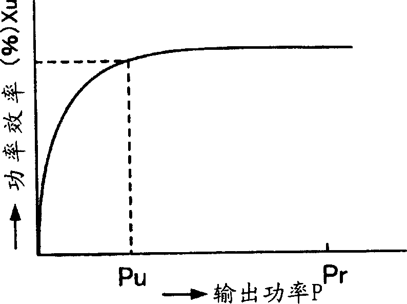
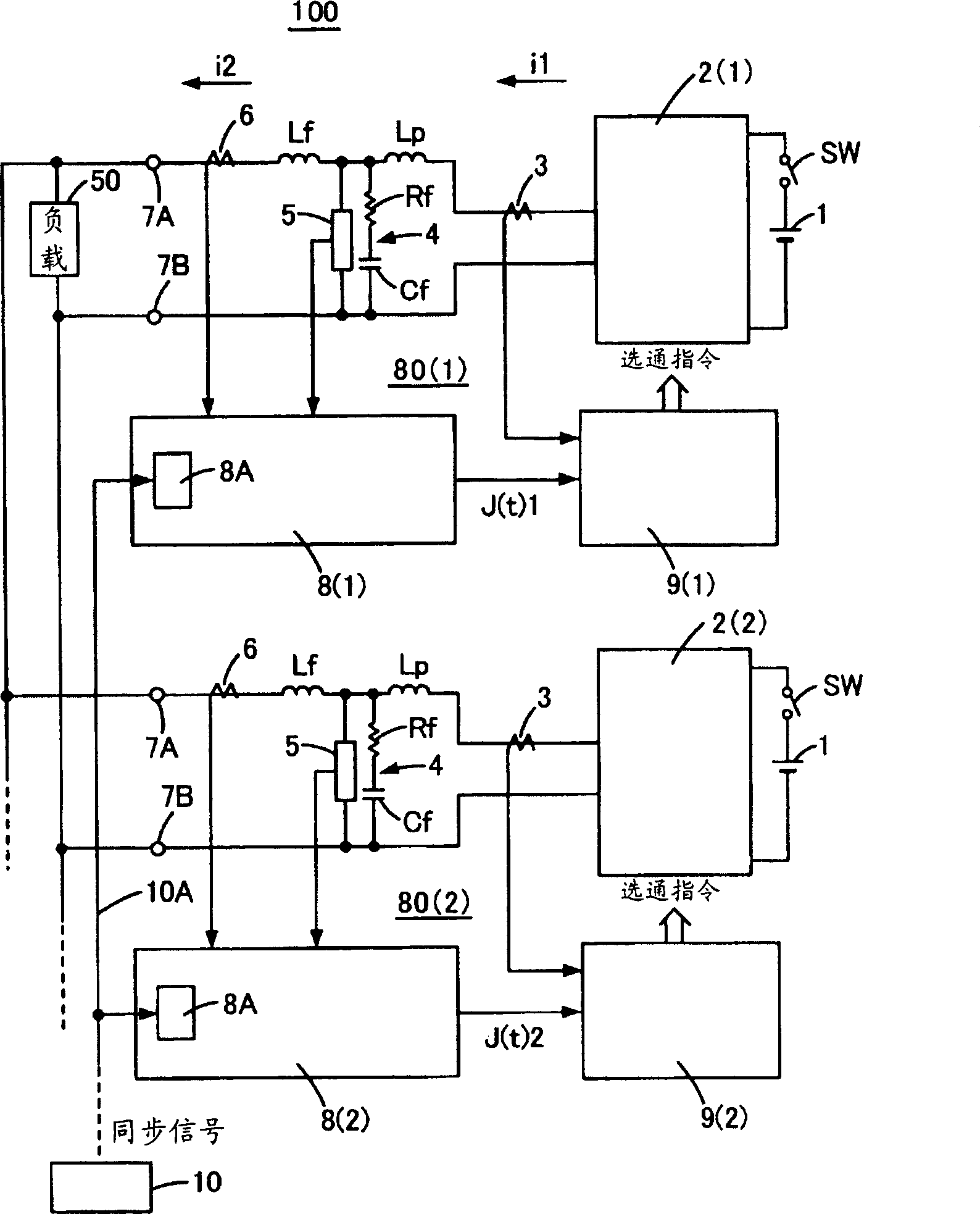
[0084] pass Figure 1 to Figure 3 , Embodiment 1 for carrying out the present invention will be described. figure 1 It is a diagram for explaining a constant sampling type error tracking type single-phase inverter device 80 of an embodiment of an inverter device that can change the equivalent internal impedance only by controlling parameters used in the present invention, figure 2 It is a graph showing an example of the power efficiency of the inverter device 80 . image 3 It is a diagram for explaining a single-phase power supply device 100 according to an embodiment of the present invention configured by connecting N inverter devices 80 in parallel. First, after passing figure 1 When describing the constant sampling type error tracking type single-phase inverter device 80 constituted by a single-phase inverter, the inverter 2 is connected to both ends of the DC power supply 1 . The DC power supply 1 is a general DC power supply, such as a rectifier or a solar panel that ...

Embodiment approach 2

[0114] In the above embodiments, the single-phase error tracking type inverter device, the error tracking type power supply device connected in parallel, and their connection and interruption (pause) have been described. However, connecting multiple constant sampling devices in parallel The limitation of the cross-current current in the constant-sampling type error-tracking power supply device composed of a three-phase AC error-tracking inverter device is also carried out in the same way. Therefore, using Figure 4 , Figure 5 A three-phase AC power supply device 200 configured by connecting a plurality of three-phase AC error tracking inverter devices 90 in parallel will be described. exist Figure 4 , Figure 5 in, with figure 1 or image 3 The same reference numerals used in indicate the same names. This second embodiment also uses a microcomputer MC, and although an A / D conversion circuit is not shown in particular, each analog detection signal is converted into a dig...

Embodiment approach 3

[0137] In the invention of Embodiment 3, the following example is shown: an inverter that exhibits an equivalent internal impedance Z approximately equal to a resistance value represented by the formula (1-β·G) / (α·G)[Ω] devices such as figure 1 As shown, and the aforementioned constant sampling type error tracking inverter device (single-layer AC power supply device) 80(1), 80(2), such as image 3 Inverter devices 100 connected in parallel as shown are in operation, and one inverter device is disconnected or connected, or the inverter device 100 is disconnected from the commercial AC power system. Of course, three or more constant sampling type error tracking inverter devices may be connected in parallel. The following description can also be applied to a case where a constant sampling type error tracking type inverter device is connected in parallel.

[0138] exist image 3 In the inverter device 100, the reference sine wave voltages of the inverter devices 80(1), 80(2) ar...


PUM


Abstract

The objective of the present invention is to provide a power source and operational method in which a plurality of inverters are connected in parallel with the ability to suppress the crosscurrent with a very simple means. The present invention is an electric power source in which a plurality of inverted operate on the same frequency and the plurality of inverters are connected in parallel so that a resistance value expressed by (1-beta.G)/(alpha.G) here alpha is the output voltage feedback gain, beta is the output current feed forward gain, and G is the inverter current gain, is made to be the equivalent output impedance; and is an electrical power source in which the cross-current between the inverters are made to be an acceptable value or below by adjusting the output of each of the inverters by controlling the equivalent output impedance by modifying both or either one of the output voltage feedback gain alpha or the output current feed forward gain beta.

Description

technical field [0001] The present invention relates to an operating method of an inverter device capable of changing an output current by adjusting an equivalent internal impedance only by controlling parameters, and an inverter device. Background technique [0002] In the case of an uninterruptible power supply device for communication, there are a plurality of storage batteries connected in series, but these storage batteries sometimes have very low terminal voltages after power failure or diagnosis. Since there is a danger that a surge current, that is, a large inrush current will flow when the power switch is turned on in such a state, and damage the switching elements, etc., so the power supply device has an inrush current prevention circuit for preventing the inrush current, or a soft A switching element in an inverter device or the like is started, that is, a soft start control is performed in which the pulse width is first decreased and then gradually increased. Ho...

Claims


Application Information

Patent Timeline
IPC IPC(8): H02H7/122H02J3/38
Inventor 大岛正明宇敷修一福井二郎
Owner ORIGIN ELECTRIC CO LTD
Why Eureka
Try Eureka