Electrical power source, operational method of the same, inverter and operational method of the same
A method of operation and inverter technology, applied to emergency protection circuit devices, irreversible DC power input to AC power output, electrical components, etc., can solve complex, reliability-reduced, unpreventable problems, etc.
- Summary
- Abstract
- Description
- Claims
- Application Information
AI Technical Summary
Problems solved by technology
Method used
Image
Examples
Embodiment approach 1
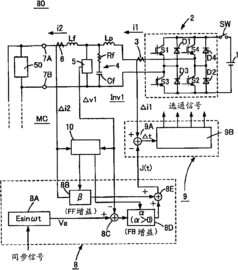
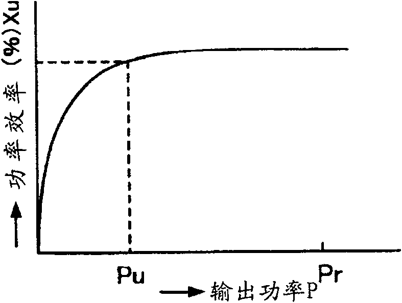
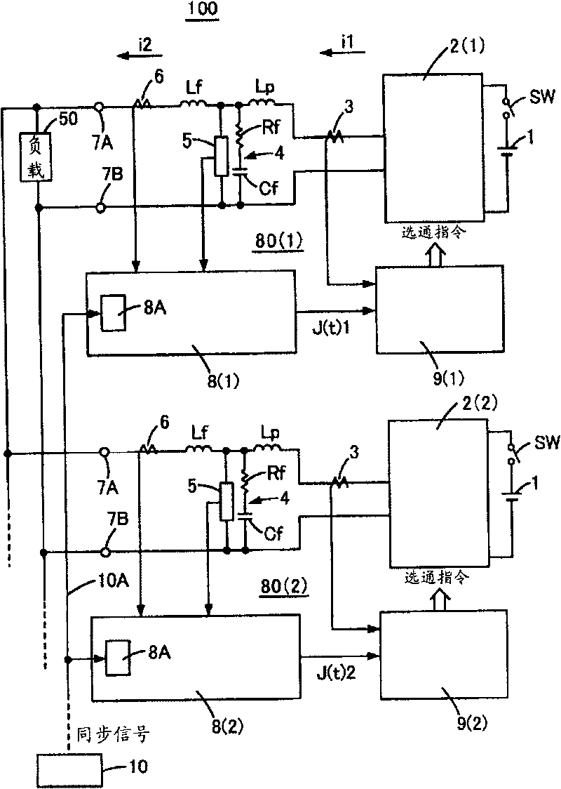
[0083] pass Figure 1 to Figure 3 , Embodiment 1 for carrying out the present invention will be described. figure 1 It is a diagram for explaining a constant sampling type error tracking type single-phase inverter device 80 of an embodiment of an inverter device that can change the equivalent internal impedance only by controlling parameters used in the present invention, figure 2 It is a graph showing an example of the power efficiency of the inverter device 80 . image 3 It is a diagram for explaining a single-phase power supply device 100 according to an embodiment of the present invention configured by connecting N inverter devices 80 in parallel. First, after passing figure 1 When describing the constant sampling type error tracking type single-phase inverter device 80 constituted by a single-phase inverter, the inverter 2 is connected to both ends of the DC power supply 1 . The DC power supply 1 is a general DC power supply, such as a rectifier or a solar panel that ...
Embodiment approach 2
[0113] In the above embodiments, the single-phase error tracking type inverter device, the error tracking type power supply device connected in parallel, and their connection and interruption (pause) have been described. However, connecting multiple constant sampling devices in parallel The limitation of the cross-current current in the constant-sampling type error-tracking power supply device composed of a three-phase AC error-tracking inverter device is also carried out in the same way. Therefore, using Figure 4 , Figure 5 A three-phase AC power supply device 200 configured by connecting a plurality of three-phase AC error tracking inverter devices 90 in parallel will be described. exist Figure 4 , Figure 5 in, with figure 1 or image 3 The same reference numerals used in indicate the same names. This second embodiment also uses a microcomputer MC, and although an A / D conversion circuit is not shown in particular, each analog detection signal is converted into a dig...
Embodiment approach 3
[0136] In the invention of Embodiment 3, the following example is shown: an inverter that exhibits an equivalent internal impedance Z approximately equal to a resistance value represented by the formula (1-β·G) / (α·G)[Ω] devices such as figure 1 As shown, and the aforementioned constant sampling type error tracking inverter device (single-layer AC power supply device) 80(1), 80(2), such as image 3 Inverter devices 100 connected in parallel as shown are in operation, and one inverter device is disconnected or connected, or the inverter device 100 is disconnected from the commercial AC power system. Of course, three or more constant sampling type error tracking inverter devices may be connected in parallel. The following description can also be applied to a case where a constant sampling type error tracking type inverter device is connected in parallel.
[0137] exist image 3 In the inverter device 100, the reference sine wave voltages of the inverter devices 80(1), 80(2) ar...
PUM
 Abstract
Description
Claims
Application Information
 - R&D
- Intellectual Property
- Life Sciences
- Materials
- Tech Scout
- Unparalleled Data Quality
- Higher Quality Content
- 60% Fewer Hallucinations
Browse by: Latest US Patents, China's latest patents, Technical Efficacy Thesaurus, Application Domain, Technology Topic, Popular Technical Reports.
© 2025 PatSnap. All rights reserved.Legal|Privacy policy|Modern Slavery Act Transparency Statement|Sitemap|About US| Contact US: help@patsnap.com


