Llc resonant converter

一种谐振转换器、谐振电容器的技术,应用在高效电力电子转换、输出功率的转换装置、有中间变换为交流的变换设备等方向,能够解决增益下降等问题,达到抑制突入电流、实现小型化、缓和压力的效果

Active Publication Date: 2019-09-10
OMRON CORP
View PDF15 Cites 3 Cited by
  • Summary
  • Abstract
  • Description
  • Claims
  • Application Information

AI Technical Summary

Problems solved by technology

On the other hand, in normal control that assumes the inductive range, the operating frequency is lowered to obtain the desired output voltage Vo ( Figure 14 point 2 → point 3), as a result, the gain further decreases, and the output voltage Vo gradually decreases

Method used


Image

  • Llc resonant converter
  • Llc resonant converter
  • Llc resonant converter

Examples


Embodiment Construction

[0091] Hereinafter, embodiments of the present invention will be described with reference to the drawings.

[0092]

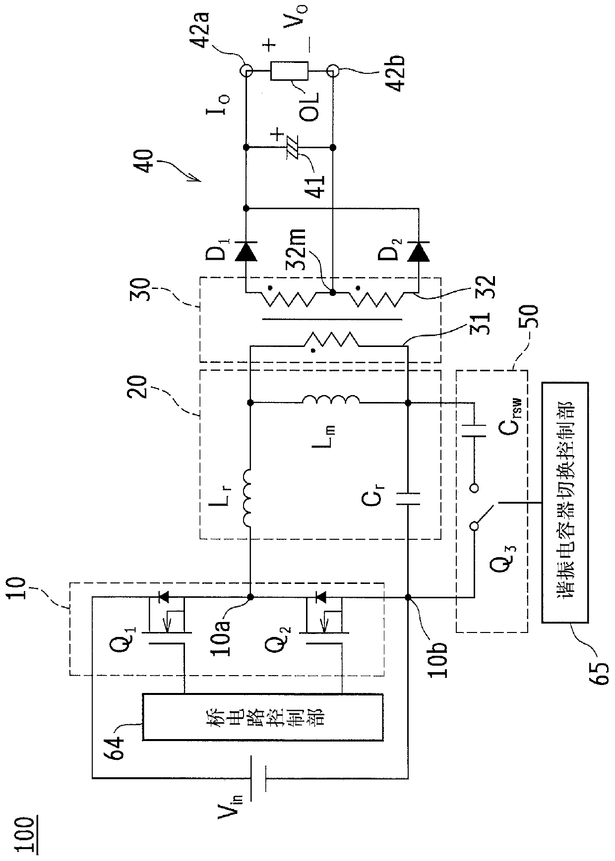
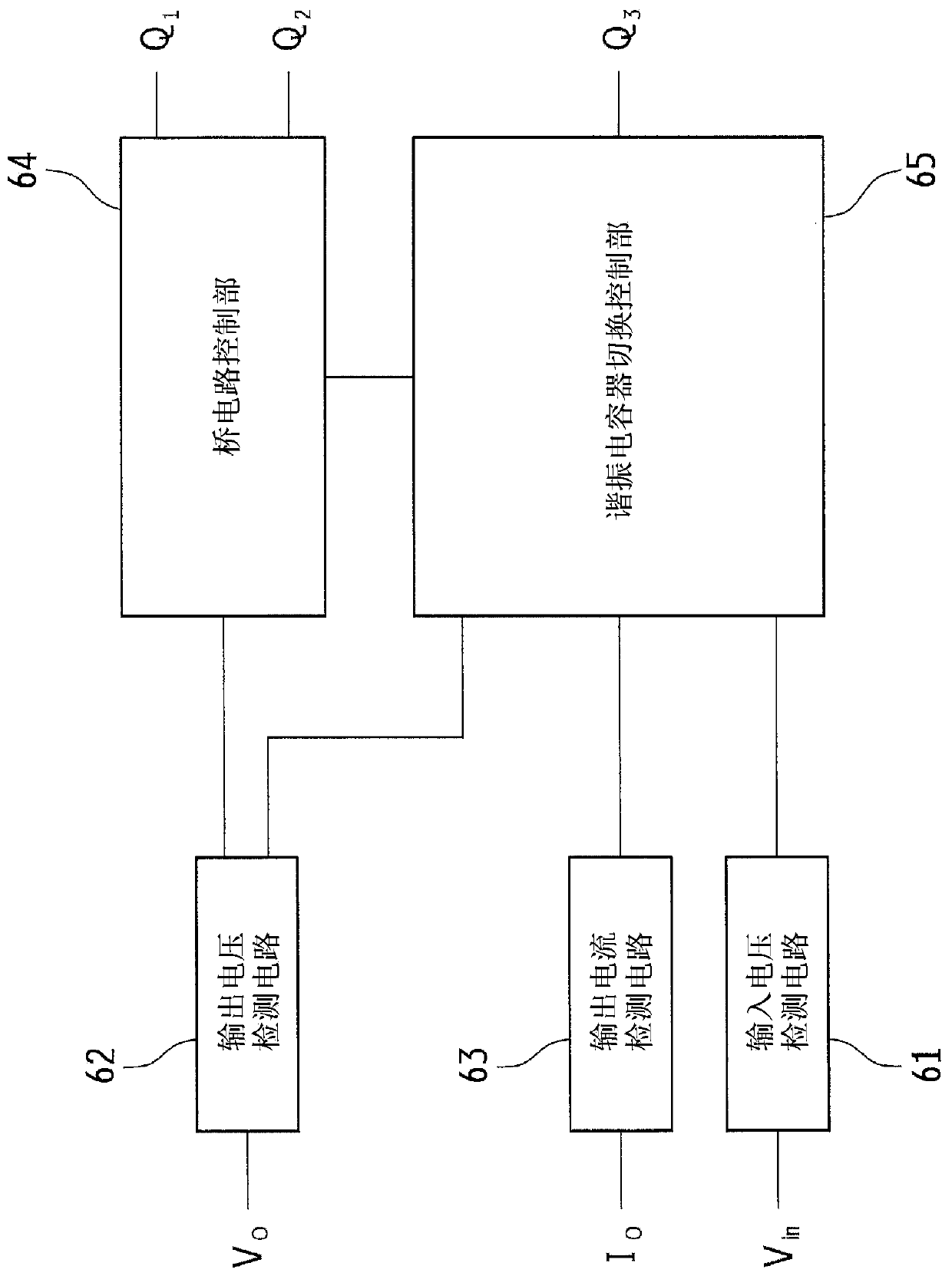
[0093] figure 1 It is a circuit diagram showing a schematic configuration of main parts of LLC resonant converter 100 according to one embodiment of the present invention. figure 2 is a block diagram showing a schematic configuration of a control unit of the LLC resonant converter 100 .

[0094] Such as figure 1 As shown, the LLC resonant converter 100 has: a bridge circuit 10 to which a DC input voltage Vin is applied; an LLC resonant circuit 20 connected to the bridge circuit 10; a transformer 30 connected to the LLC resonant circuit 20; a rectifier circuit 40 , which is connected to the transformer 30 and outputs the converted DC voltage; a resonant capacitor switching circuit 50 ; a bridge circuit control unit 64 ; and a resonant capacitor switching control unit 65 .

[0095] The bridge circuit 10 has a switch Q1 and a switch Q2 connected in series,...


PUM


Abstract

This LLC resonant converter (100) is provided with: a bridge circuit (10) to which a DC input voltage (Vin) is applied; an LLC resonance circuit (20) connected to the bridge circuit (10); a transformer (30) connected to the LLC resonance circuit (20); a rectifier circuit (40) connected to the transformer (30) and outputting a DC voltage after conversion; a resonance capacitor switching circuit (50); a bridge circuit control unit (64); and a resonance capacitor switching control unit (65). When the input voltage (Vin) exceeds a switching voltage, an operating frequency is increased to a frequency higher than a resonance frequency, and then a switch (Q3) is turned off.

Description

technical field [0001] The present invention relates to a direct current voltage converter (DC-DC converter) for converting a direct current voltage into another direct current voltage, and particularly relates to an LLC resonance which is an example of a representative circuit of an isolated DC-DC converter using a switch pair corresponding to an input voltage The resonant capacitor of the converter performs switching control. Background technique [0002] Figure 5 It is a circuit diagram showing a schematic configuration of an LLC current resonant converter 1 as an example of a conventional LLC resonant converter. [0003] as it should Figure 5 As shown, the LLC current resonance converter 1 has: a bridge circuit 10 to which a DC input voltage Vin is applied; an LLC resonant circuit 20 connected to the bridge circuit 10; a transformer 30 connected to the LLC resonant circuit 20; And a rectification circuit 40, which is connected to the transformer 30 and outputs the con...

Claims


Application Information

Patent Timeline
Patent Type & Authority Applications(China)
IPC IPC(8): H02M3/28
CPCH02M1/32H02M1/36H02M1/4208Y02B70/10Y02P80/10H02M1/0009H02M1/0058H02M1/325H02M7/4818H02M3/33571H02M3/01H02M3/33507H02M1/08
Inventor 佐藤充长冈真吾大西浩之
Owner OMRON CORP
Why Eureka
Try Eureka